2 fieldbus / devicenet leds, 3 devicenet node address switches – BECKHOFF IPxxxx-B520 User Manual
Page 35
Indicators and Switches
IPxxxx-B520
32
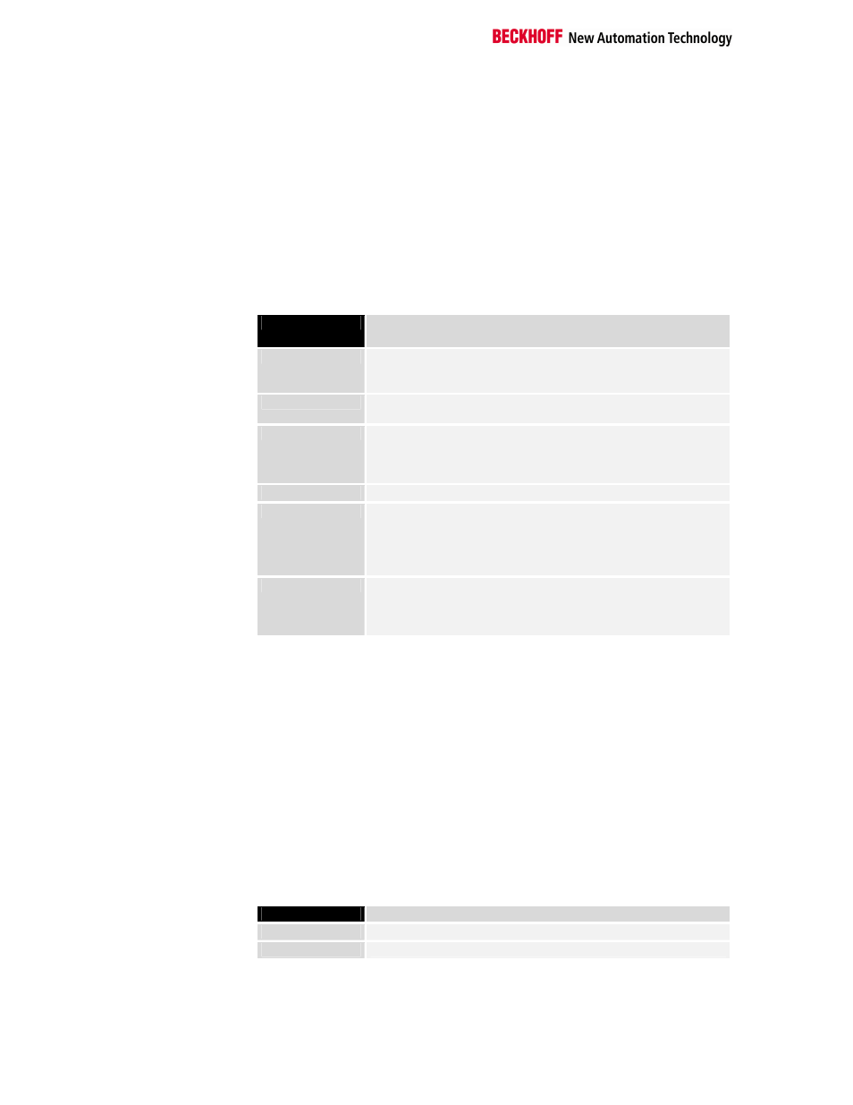
10.2 Fieldbus / DeviceNet LEDs
DeviceNet Status LED
The red/green LED pair provides information about the device and com-
munication status of the IPxxxx-B520. The LEDs acts as the bi-color com-
bined Module/Network Status LED defined in the DeviceNet Specification.
The LED Pair is located next to the configuration interface for adjustment of
the DeviceNet address (MacId)
States of Module / Status
LED
LED State
Description
Green Flashing
Boot Up OK, Device has executed Duplicate MacId Check and
is ON-Line. The IPxxxx-B520 is not allocated by a Master /
Scanner, no Data Exchange with a Master / Scanner
Green ON
No Error, IPxxxx-B520 is allocated by a Master / Scanner, Data
Exchange (Explicit or IO) with Master / Scanner is OK
Green OFF
- Bus Sense Error (24V DeviceNet Voltage in not available)
(all LEDs off, including IO-Run, IO-Error LEDs)
- No BaudRate, IPxxxx-B520 is not able to detect BaudRate
(IO-Run, IO-Error LEDs On)
Red Flashing
Time Out, IO-Connection has timed out
Red ON
- Duplicate MacId Fault, check for same Address in Network
- Bus-Off, check cabling, check bus termination, check bus
length
- Receive/Transmit Overrun, reduce IO-Cycle Time / Interscan
delay at Master / Scanner
Red OFF
- Bus Sense Error (24V DeviceNet Voltage in not available)
(all LEDs off, including IO-Run, IO-Error LEDs)
- No BaudRate, IPxxxx-B520 is not able to detect BaudRate
(IO-Run, IO-Error LEDs On)
10.3 DeviceNet Node Address Switches
Node Address Switches
The Node Address Switches consist of two, ten position rotary switches
within the Configuration Interface of the IPxxxx-B520
Node Address Switches
Node Address Switch
Node Address
Description
0 - 63
Node Address from Switches is valid, not programmable
> 63
Node Address is programmable by Master / Scanner