BECKHOFF KL6051 User Manual
Page 12
Register description
12
KL6051
Control byte in the
register mode
MSB
REG=1
W/R
A5
A4
A3
A2
A1
A0
REG = 0 : Process data transfer
REG = 1 : Access to register structure
W/R = 0 : Read register
W/R = 1 : Write register
A5..A0 = Register address
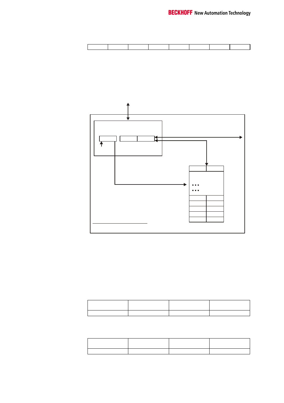
A total of 64 registers can be addressed with the addresses A5....A0.
0
63
Terminal´s
register set
64 words
Control-/
status byte
User data
K-Bus
If control bit 7=0: input/output
If control bit 7=1:
register-
configuration
C/S-bit 7
If control bit 7=1:
adress in the control bit 0-5
If control bit 6=0: read
If control bit 6=1: write
Complex bus terminal
To the bus coupler
H
H
L
L
2 or mors bytes
The control or status byte occupies the lowest address of a logical channel.
The corresponding register values are located in the following 2 data bytes
(the BK2000 is an exception to the rule: here, an unused data byte is inser-
ted after the control or status byte, thus setting the register value to a word
limit).
Example
Reading register 8 in the BK2000 with a Kl3022 and the end terminal.
If the following bytes are transferred from the controller to the terminal,
Byte0
Control
Byte1
Not used
Byte2
Data OUT, high byte
Byte3
Data OUT, low byte
0x88
0xXX
0xXX
0xXX
the terminal returns the following type designation (0x0BCE corresponds to
the unsigned integer 3022).
Byte0
Status
Byte1
Not used
Byte2
Data IN, high byte
Byte3
Data IN, low byte
0x88
0x00
0x0B
0xCE