3 description of functions, 4 operating modes – BECKHOFF KL2502 User Manual
Page 8
Product overview
6
KL2502, KL2512
2.3 Description of functions
The output terminal KL2502 modulates the pulse width of a binary signal.
The peripheral end of the electronic circuitry is electrically isolated from the
internal K bus and therefore also from the field bus. The clock pulse (base
frequency) and the pause ratio are adjustable. Via the control system’s
process image, 16-bit values can be specified for setting.
By default, the terminal KL2502 occupies 6 bytes in the process image.
Mapping of the KL2502 is adjustable via the control system or via the bus
coupler’s configuration interface using the Beckhoff KS2000 configuration
software.
Besides operation in the PWM mode, the KL2502 can also be operated in
the FM mode (frequency modulation) or in the stepper motor control mode
(Frq-Cnt-Pulse mode).
The terminal’s default setting is the PWM mode with a base frequency of
250 Hz and a resolution of 10 bits.
LED display
RUN LEDs
On: normal operation
Off: watchdog timer overflow has occurred. If no process data is transferred
by the bus coupler for 100 ms, the green LED goes off and the outputs are
set to 0% duty cycle.
Process data
Input format:
KL2502: 2‘s complement representation (integer -1 corresponds to 0xFFFF)
The duty cycle/period ratio is specified with a maximum resolution of 10 bits.
KL2512: 16 bit unsigned Integer
process data
output value
KL2502
KL2512*
0% duty cycle
0x0000 (0
dez
)
0x7FFF (32767
dez
)
0xFFFF (65535
dez
)
50% duty cycle
0x3FFF (16383
dez
)
0x3FFF (16383
dez
)
0xBFFF (49151
dez
)
100% duty cycle
0x7FFF (32767
dez
)
0x0000 (0
dez
)
0x8000 (32768
dez
)
*) The KL2512 runs twice trough the output range (0...100% duty cycle).
2.4 Operating modes
The operating mode of the terminal is set via the feature register R32.
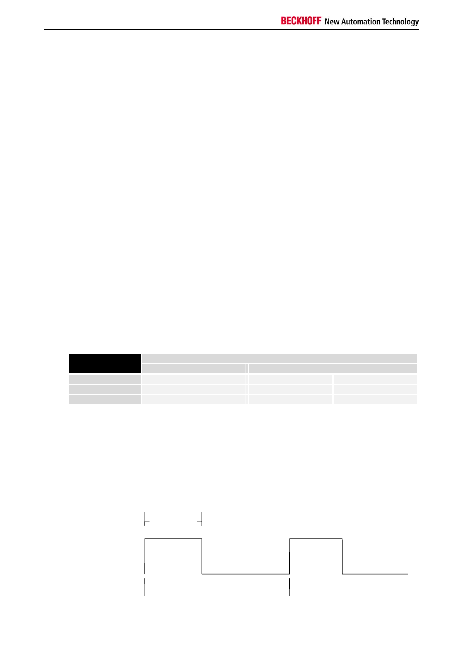
PWM mode
In the PWMx modes, two channels can be operated. Attention must be paid
to the fact that the operating mode and the period are identical for both
channels.
Duty-Cycle
Period
t