BECKHOFF KL2502 User Manual
Page 19
Terminal
configuration
KL2502, KL2512
17
3.4.1 Examples
Each terminal channel is mapped in the bus coupler. The terminal’s data is
mapped differently in the bus coupler’s memory depending on the type of
the bus coupler and on the set mapping configuration (e.g. Motorola / Intel
format, word alignment,...). Contrary to the analog input and output
terminals, in the case of the KL2502 the control and status byte is always
also mapped regardless of the field bus system used.
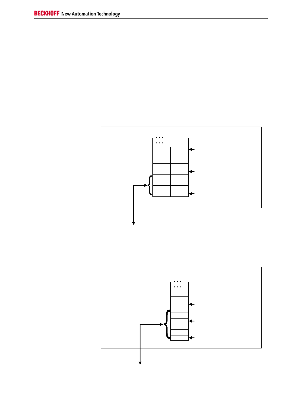
Lightbus Coupler BK2000
In the case of the Lightbus Coupler BK2000, the control /status byte is
always mapped besides the data bytes. It is always in the low byte at the
offset address of the terminal channel.
0
Offset Terminal1 Channel1 = 0
Offset Terminal2 Channel1 = 4
KL2502
Offset Terminal2 Channel2 = 8
User data allocation depending
on mapping
K-Bus
Beckhoff-Lightbus
bus coupler
BK2000
To the bus terminal
L
H
C/S - 0
D0 - 0
D0 - 1
D1 - 0
D1 - 1
C/S - 1
C/S
C/S
Data L
Data H
Data H Data L
C/S
The terminal is
mapped in the
bus coupler.
Profibus Coupler BK3000
In the case of the Profibus coupler BK3000, by default the KL2502 is
mapped with 6 bytes of input data and 6 bytes of output data (3 bytes per
channel). Therefore, 2 bytes of user information data and 1 control/status
byte are mapped for each channel.
Offset Terminal1 Channel1 = 0
Offset Terminal1 Channel2 = 3
Offset Terminal2 Channel1 = 6
KL 2502 Channel1
KL 2502 Channel 2
The control-/status byte
must be inserted for
parameterization.
K-Bus
Profibus bus coupler
BK3000
To the bus terminal
Data H
Data L
D1 - 0
D0 - 0
D0 - 1
D1 - 1
C/S - 0
C/S
C/S - 1
0
The terminal is
mapped in the
bus coupler.