Communication connections and settings, Communication connector, Communication settings – Basler Electric BE1-79A 9310200114 User Manual
Page 42: Communication connections and settings -6, Communication connector -6, Communication settings -6, Figure 5-4. pc to be1-79a connections -6, Table 5-1. rs-232 pin functions -6
Communication Connections and Settings
The required connections and settings for BE1-79A communication are described in the following
paragraphs.
Communication Connector
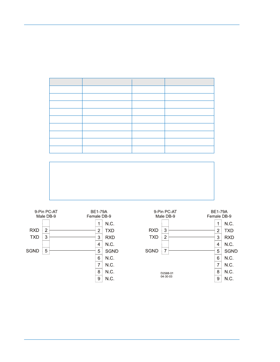
The BE1-79A uses a standard RS-232 (DB-9) female connector located on the front panel. Connector pin
numbers, functions, names, and signal directions are listed in Table 5-1. Figure 5-4 provides a connection
diagram for connecting the BE1-79A relay to a personal computer (PC).
Table 5-1. RS-232 Pin Functions
Pin
Function
Name
Direction
1
Shield
—
N/A
2
Transmit Data
TXD
From Relay
3
Receive Data
RXD
Into Relay
4
N/C
—
N/A
5
Signal Ground
GND
N/A
6
N/C
—
N/A
7
N/C
—
N/A
8
N/C
—
N/A
9
N/C
—
N/A
NOTE
The RS-232 communication ports are not equipped with request-to-send
(RTS) and clear-to-send (CTS) control lines. This makes the BE1-79A
incompatible with systems that require hardware handshaking or systems that
use self-powered RS-232 to RS-485 converters connected to the RS-232
ports.
Figure 5-4. PC to BE1-79A Connections
Communication Settings
Communication settings are the formal set of conventions controlling the format and relative timing of
message exchange between two communication terminals. The BE1-79A settings are fixed at 9600, 8N1,
where 9600 is the baud rate, 8 is the number of data bits, N is the parity (none), and 1 indicates one stop
bit. Since the communication settings of the relay are fixed, you must adjust your communication program
settings to match the relay settings. Information about configuring Windows
® HyperTerminal for
communication with the BE1-79A is provided in Appendix B, Terminal Communication.
5-6
BE1-79A Installation and Configuration
9310200893 Rev C