Interconnections, Interconnections -4, Figure 3-2. relay interconnections -4 – Basler Electric BE1-79A 9310200114 User Manual
Page 24: Be1-79a
Interconnections
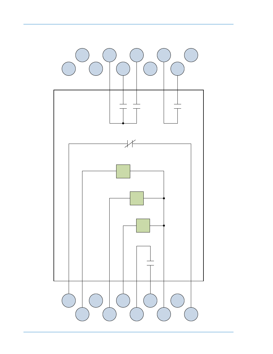
Figure 3-2 illustrates the interconnection of the contact sensing inputs, relay outputs, style configuration
switches, instantaneous reclose jumper switch, and RS contact configuration switch in the BE1-79A relay.
The state of all relay output contacts is shown with all power removed from the relay.
Figure 3-2. Relay Interconnections
11
12
13
14
15
16
17
18
19
20
1
2
3
4
5
6
7
8
9
10
Close
Close
Alt. 1
Close
Alt. 2
P
0
0
6
4
-8
3
Lockout
RS
Power
Supply
52b
52a
BE1-79A
3-4
BE1-79A Functional Description
9310200893 Rev C
See also other documents in the category Basler Electric Relay:
- BE1-11i RTD Module (672 pages)
- BE1-11m Terminals and Connectors (604 pages)
- BE1-11i RTD Module (554 pages)
- BE1-11 DNP3 Protocol (82 pages)
- BE1-11 IEC 61850 Protocol (100 pages)
- BE1-11 Modbus Protocol (186 pages)
- BE1-851 (364 pages)
- BE1-851E DNP3 Protocol (40 pages)
- BE1-851E Modbus Protocol (70 pages)
- BE1-700 (460 pages)
- BE1-700 Modbus Protocol (92 pages)
- BE1-50 (44 pages)
- BE1-50/51B (76 pages)
- BE1-50/51M (74 pages)
- BE1-50/51B-122 (66 pages)
- BE1-50/51B-232 (64 pages)
- BE1-50/51B-231 (60 pages)
- BE1-50/51B-233 (60 pages)
- BE1-50/51B-240 (52 pages)
- BE1-50/51B-241 (52 pages)
- BE1-50/51B-244 (64 pages)
- BE1-50/51B-225 (72 pages)
- BE1-50/51B-228 (68 pages)
- BE1-50/51B-226 (52 pages)
- BE1-50/51B-236 (68 pages)
- BE1-50/51B-239 (76 pages)
- BE1-50/51B-238 (70 pages)
- BE1-51 (100 pages)
- BE1-64F (30 pages)
- BE1-51/27C (112 pages)
- BE1-25 (66 pages)
- BE1-51/27R (114 pages)
- BE1-87G (68 pages)
- BE1-59N (40 pages)
- BE3-25 (2 pages)
- BE3-27T/59T (2 pages)
- BE3-27/59 (2 pages)
- BE3-32 (2 pages)
- BE1-32O/U (82 pages)
- BE3-47 (2 pages)
- BE3-37/51 (2 pages)
- BE3-47N/27 (2 pages)
- BE3-49R-3 Inputs (2 pages)
- BE3-49R-6 Inputs (2 pages)
- BE3-49TL (2 pages)