Time pickup test – Basler Electric BE1-50/51B-121 User Manual
Page 48
5-4
BE1-50/51B-214/-215/-223/-225 Testing
9252000994 Rev P
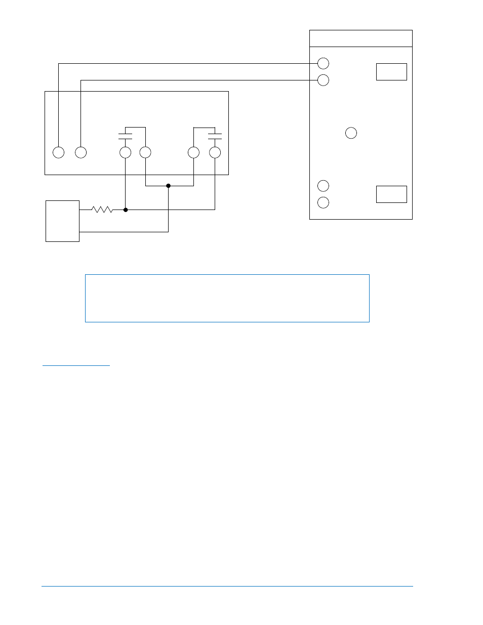
Figure 5-6. Target Operational Test Setup, BE1-50/51B-223
NOTE
When testing TIME overcurrent functions, INST PICKUP settings of 00 will
affect the calibration of the TIME functions. TIME PICKUP settings of 00 also
affect INST functions.
Test Procedure, Models BE1-50/51B-214/-215/-223 (Five Ampere Sensing Input)
Perform preliminary setup:
Time Pickup Test
•
Connect test setup as shown in Figure 5-1 (BE1-50/51B-214), Figure 5-3 (BE1-50/51B-215), or
Figure 5-5 (BE1-50/51B-223).
•
Insure that SW3 switches are set: SW3-1 for the operating frequency, SW3-2 to OFF, SW3-3 to
ON and SW3-4 to ON.
•
Set TIME DIAL to 0.0.
•
Set CURVE to S
•
Set TIME PICKUP to 0.5.
•
Set INST PICKUP to 90.
Step 1. Slowly increase current to terminals 5 and 6. PICKUP LED should turn RED at a maximum input
current of 0.550 ampere.
Step 2. Decrease input current until PICKUP LED turns GREEN then OFF.
Step 3. Set TIME PICKUP to 2.2.
Step 4. Slowly increase current to terminals 5 and 6. PICKUP LED should change from GREEN to RED
at an input current of 2.131 to 2.269 amperes.
Step 5. Decrease input current until PICKUP LED turns OFF.
BE1-50/51B-223
6
5
10
1
TIME
INST
2
CURRENT
SOURCE
INPUT
STOP
TIMER
START
AMPS
TEST SET
P0061-21
9
R
AC or DC
Voltage
Source
(V)
1 A Target Current
R = V/1
Rwatts = 1*V