Nsert, Nstallation, Approved vent configurations restrictor position – Avalon Firestyles Chelan DV-1996 to 1999 User Manual
Page 19: Electrical connection
I
NSERT
I
NSTALLATION
(C
ONT
.)
- For Qualified Installers Only!
P
AGE
19
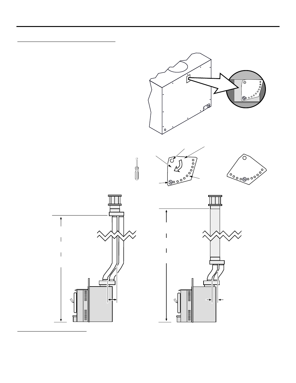
Approved Vent Configurations
Restrictor Position
¥
A vent restrictor is
built into the
appliance to adjust
the flow rate of
exhaust gases. This
ensures proper
flames for the wide
variety of vent
configurations. The
restrictor consists of
a butterfly valve
below the starter
section of pipe and
an adjustment plate
with index holes used
to hold the valve in a
fixed position. Use
the illustrations
below to determine
the correct restrictor
position.
To Adjust the Restrictor:
1
2
3
4
The eleven holes on the
restrictor plate
correspond to the eleven
restrictor positions.
NOTE:
Position #1 is the
fully open position
Determine the correct
restrictor position (see the
charts under "Approved
Vent Configurations" - the
stock position is #1).
Remove the screw with a
1/4" nutdriver (or
screwdriver).
Rotate the adjustment plate
clockwise until the correct
index hole is below the pivot
point.
Insert the screw into the
correct index hole and
tighten.
Adjustment
Plate
1/4" Nutdriver
Index Holes
Pivot Point
This restrictor is
in Position #5.
Screw
Rotate the
adjustment
plate to change
the restrictor
position.
1 2 3
4
5
6
7
8
9
10
11
1' offset
(max.)
1' offset
(max.)
10' - 24'
Use restrictor position 7
Max. Ht. 30'
Min. Ht. 10'
Full Flex Re-Line
Co-Axial Vent Re-Line
24' - 30'
Use restrictor position 5
10' - 16'
Use restrictor position 5
Max. Ht. 30'
Min. Ht. 10'
16' - 30'
Use restrictor position 7
Electrical Connection
¥
Plug the power cord into a grounded 120 Volt outlet (do not remove the grounding plug).