Commlink ii installation, Ez zone/auto-zone upgrade 25, Figure 13: commlink ii wiring – Auto-Zone Control Systems EZ-Zone to Auto-Zone Upgrade Guide (Version 01C) User Manual
Page 25: Commlink jumper switch settings
EZ Zone/Auto-Zone
Upgrade
25
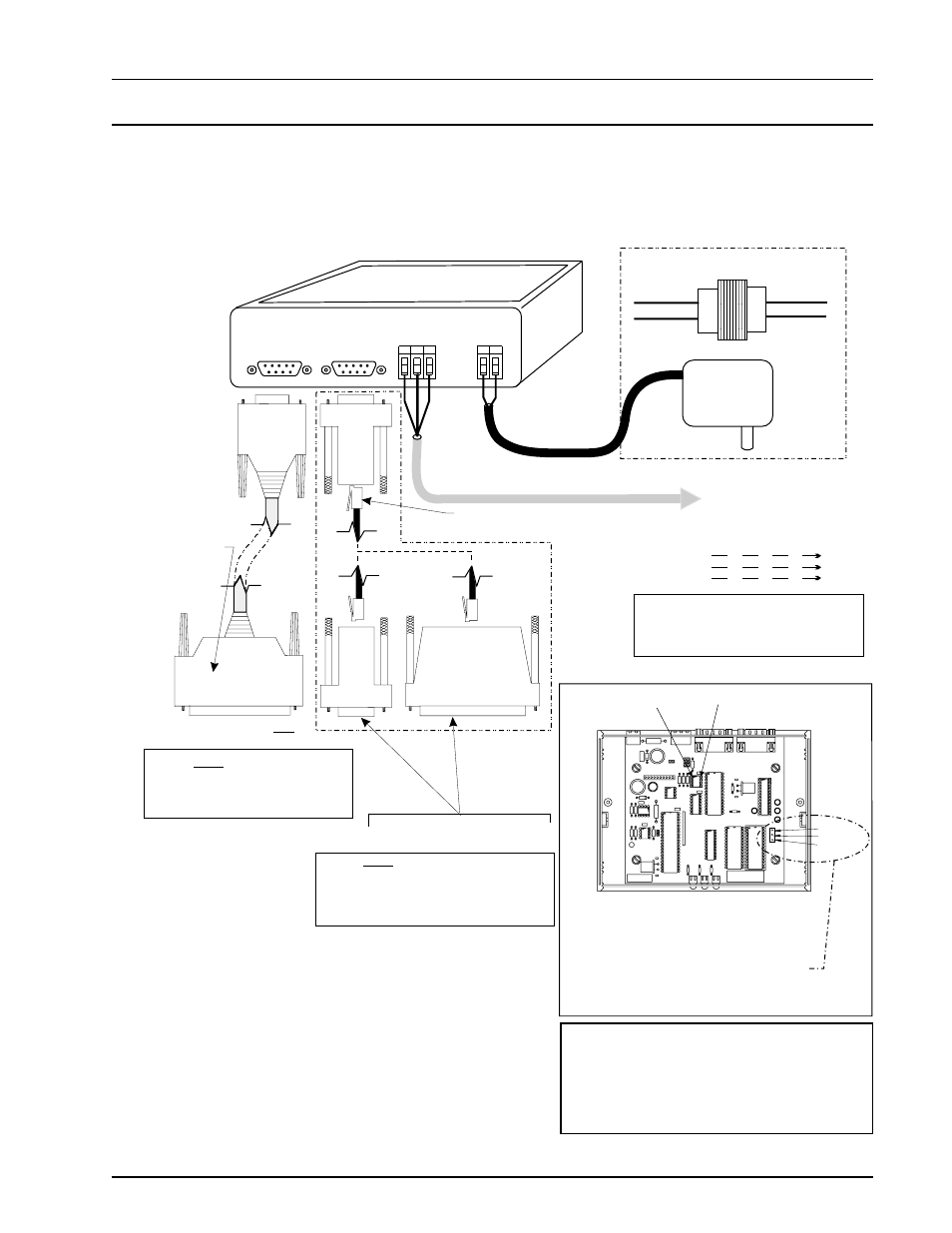
Commlink II Communications Interface
(Jumper Set For Multiple Loop)
Caution:
Use The “Molded Cable” To
Connect To The Computer (DCE) Connector.
This Cable Is Only To Be Used To Connect
From The CommLink (DTE) Connection To
The Modem (When Used).
Do Not
Caution:
Disconnect All Communication Loop Wiring
From The CommLink Before Removing Power
From The CommLink. Reconnect Power And Then
Reconnect Communication Loop Wiring.
Use 25 Pin Or 9 Pin Connector As
Required By Available Serial (COM) Port
On Computer.
Caution:
Use The “25 Pin Or 9 Pin Cable” To
Connect To The Modem (DTE) Connector.. This
Cable Is Only To Be Used To Connect From The
CommLink (DCE) Connection To The Computer
Serial Port (COM) Connection.
Do Not
(When Used)
Note:
Place Jumper Between
Pins 1 & 2 for Multiple
Loop Applications &
Between Pins 2 & 3 for
Single Loop Applications
COMM DRIVER CHIP
( U1 )
PIN 1
MULTI
SINGLE
1
2
3
CommLink Jumper Switch Settings
Notes:
R
SH
T
R
SH
T
R
SH
T
R
SH
T
All Communication Loop
Wiring Is Straight Through
Connect To First Zone
Manager On Network Loop
Network Loop
RS-485
19200 Baud
(See Note 3).
Line Voltage
See Note 1
24VAC
Required VA For Transformer
CommLink = 14VA Max.
CommLink Is Supplied With 110/24VAC Power Supply.
If Desired A Transformer (By Others)
May Be Wired To The CommLink Instead
Molded Modem Cable.
Part #HZ000098
Supplied With CommLink
(DTE)
MODEM
MODEM
485 LOOP
485 LOOP
COMPUTER
(DCE)
G
T
R
G
2
V
4
D
N
POWER
4 Piece Computer
Cable Kit.
Part # HZ000112
Supplied With
CommLink
Connect To Modem
.
Modem Is Part # OE419-02
Only
9
Pin
Female
9 Pin
Female
25 Pin
Female
9
Pin
Female
120/24 Vac
Transformer
Part # PX000015
25 Pin
Male
Part #CLMA19A1
Connect Supplied RJ12 Modular Phone Cable
To Supplied 9 Pin Or 25 Pin Connector As Reqd
By Your Computer Com Port Connection
1.)24 VAC Must Be Connected So
That All Ground Wires Remain
Common.
2.)All Wiring To Be In Accordance
With Local And National Electrical
Codes And Specifications.
3.)All Communication Wiring To Be
2 Conductor Twisted Pair With
Shield. Use Belden #82760 Or
Equivalent.
Figure 13: CommLink II Wiring
CommLink II Installation
Note:
For Auto-Zone Basic System (See Example 1 page 8
& 9) jumper must be set for single loop operation as
shown above.
For Auto-Zone Plus System (See Example 2 page 10
& 11) jumper must be set for multiple loop operation
as shown above.