Auto-zone plus wiring, Ez zone/auto-zone 18 upgrade, Zone manager – Auto-Zone Control Systems EZ-Zone to Auto-Zone Upgrade Guide (Version 01C) User Manual
Page 18: Warning, Belimo
EZ Zone/Auto-Zone
18
Upgrade
Zone Manager
Notes:
1.)24 VAC Must Be Connected So
That All Ground Wires Remain
Common.
3.)All Communication Wiring To Be 18
Ga. Minimum, 2 Conductor Twisted
Pair With Shield. Belden #82760 Or
Equivalent.
5.)For Individual Component Wiring See
Specific Component Wiring Diagram.
2.)All Wiring To Be In Accordance With
Local And National Electrical Codes
and Specifications.
RS-485
Communications To Zone
Controllers, CV Controllers
And/Or System Manager
Return Air Temp.
Sensor
Supply Air Temp.
Sensor
Line
Voltage
HV
AC
Unit
24VAC Only
Red
Blk
To Relief / Exhaust Fans
Grn
Static
Pick-up
Static
Pressure
Sensor
Splice As
Required
LO
HI
GND
24VAC
Belimo Actuator Wiring Shown
Consult Factory For Other
Models Of Economizer Actuators
Some Actuators Require Isolation
Transformers In Order To Prevent
Damage To The Controller Board.
WARNING!
Use Extreme Care When Wiring
Economizer Actuators
Never Connect Or Disconnect
Wiring With Power Applied!
Never Apply Power If The
Gnd ( 1 Com ) Terminal On The
Actuator Is Not Connected.
See Note 1 &2
+
+
+
+
+
+
+
+
+
HEAT2
HEAT1
COOL2
COOL1
FAN
R
2
8
C
SW
1
16
A
B
2
4
ADD
LOCAL
LOOP
Local Loop
T
SH
R
TB3
COMM
T
SH
R
32
16
8
4
1
2
MINILINK
R9
R10
R8
I C
EXP
PORT
PWR
V4
V3
CLOSE
OPEN
FDBK
REC
GND
GND
24VAC
AUX1
OPEN
K1
NETWORK
LOOP
Network Loop RS-485
19200 Baud
To Other Zone
Managers and/or
CommLink on
System
SH
R
T
CLOSE
K2
NE5090
ANALOG
OUTPUTS
A2
G
TB2
A1
N.O.
EXHAUST
CONTACTS
GND
GND
AUX3
AUX2
7824
D
25
U
14
V
R
3
R
40
ADJUST
5.11V
C
27
7812
C
26
V
R
2
D1
D3
D4
D2
PJ1
P
R
E
S
SU
R
E
S
E
N
S
O
R
JA
C
K
+5V
R7
OAT
RAT
+12V
SAT
ANALOG
INPUTS
GND
SIG
T
R
SHIELD
T
R
SHIELD
Outdoor Air Temp.
Sensor
(See Note 4)
Aux3
Forced
Occupied
Mode
Aux1
Economizer
Disable
Aux2
Filter
Alarm
Auxiliary Inputs
( Dry Contacts )
R
G
Y1
Y2
W1
W2
Economizer Actuator
133 IN-LB
AF24-SR
1 COM
2 +
3 Y1
4 Y2
5 U
BELIMO
Actuator Wiring
Interface
Bypass Air Damper
Actuator
4.)Only One Outside Air Sensor Is
Required Per System. It May Be
Connected To Any CV Controller Or
Zone Manager On The System. If A
Wetbulb Module Controller Is Used The
OA Sensor Must Be Connected To The
Wetbulb Module.
75
90
60
45
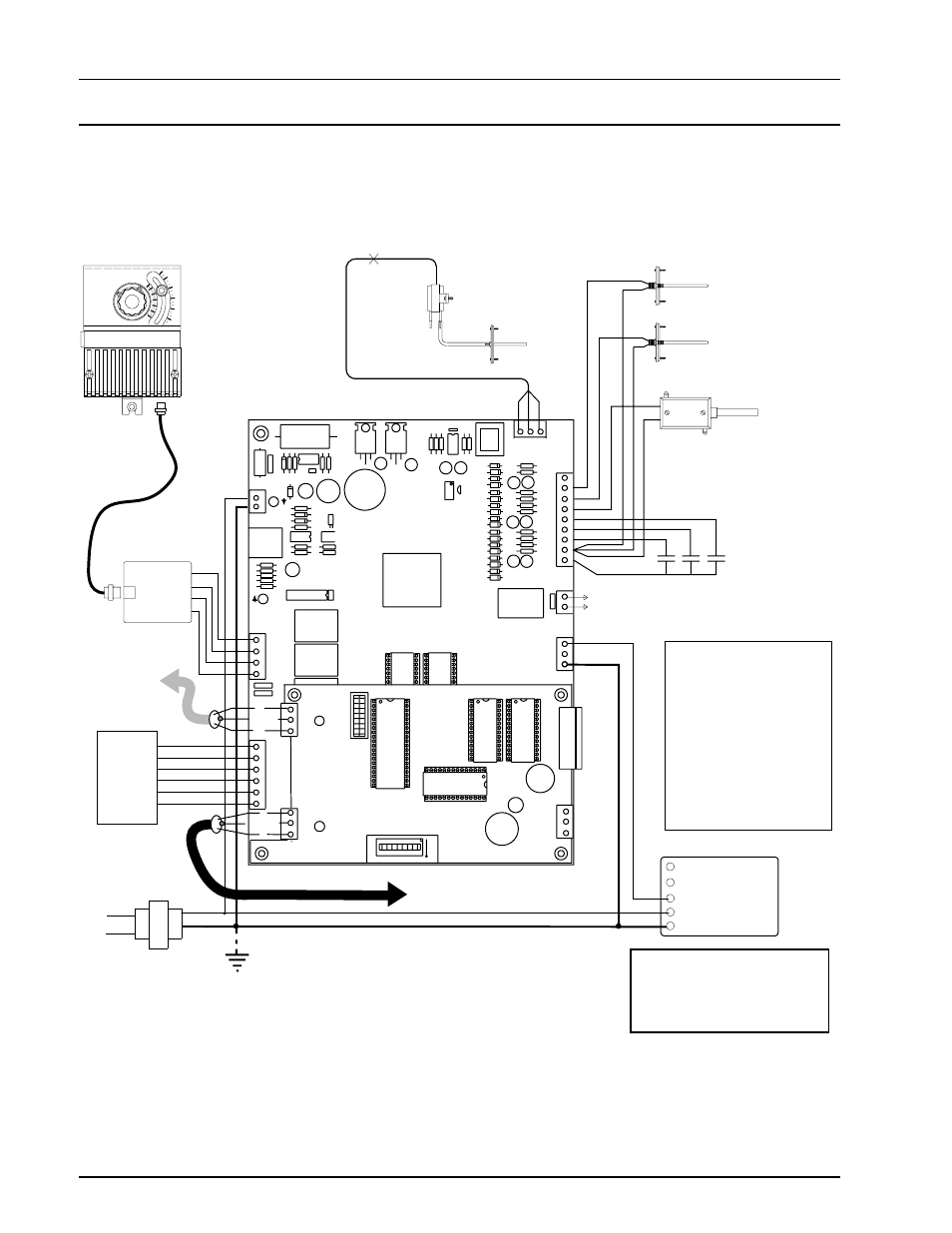
Auto-Zone Plus Wiring
Figure 3: Existing Auto-Zone Plus Controller Wiring
Figure 3 below depicts the wiring schematic that should
be used for the Auto-Zone Plus System upgrade as de-
scribed in Example 2 on pages 10 and 11 of this manual.
This schematic is also used for wiring of Example 3 on
pages 12 & 13 of this manual. Be sure to pay strict at-
tention to all warnings and cautions listed on the sche-
matic.
Warning:
See Figure 11 in this manual for
important wiring instructions
regarding Honeywell economizer
actuators