Zoning design procedures – Auto-Zone Control Systems Zoning Design Guide (Version 01B) User Manual
Page 18
18
Auto-Zone Systems
Zoning Design Guide
Zoning Design Procedures
Pressure Dependent Dampers
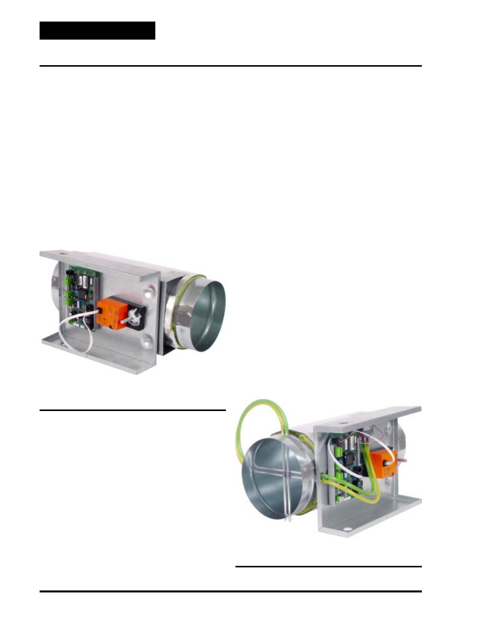
With pressure dependent (PD) dampers, the minimum
and maximum airflow is set based on damper position.
During the final commissioning of the system, each zone
is typically balanced with a flow hood and the min/max
position is fixed either mechanically or the preferred
method, in the controller software. Since this min/max
setting is based only on position, as the static pressure
fluctuates it will cause the actual airflow at the zone
damper to increase or decrease. Therefore the name,
pressure dependent since the airflow is dependent on
the static pressure. Pressure dependent dampers are
available in round or rectangular configurations. See
Figure 1-11 for a diagram of a typical pressure depen-
dent zone damper.
Pressure Independent Dampers
When using pressure independent (PI) dampers this
minimum and maximum is set based on actual CFM of
airflow through the damper. Airflow is measured using
a pickup tube mounted in the zone damper and an elec-
tronic air flow sensor. Using this method you always
know the actual airflow through each zone damper in-
stead of just the damper percentage open. The mini-
mum and maximum settings are based on this actual
airflow reading. As the static pressure fluctuates, the
flow sensor reads the variation and automatically repo-
sitions the damper to maintain the minimum or maxi-
mum flow setpoints. Since the minimum or maximum
airflow is maintained independently of the static pres-
sure available in the duct it is called pressure indepen-
Figure 1-11: Pressure Dependent Damper
Figure 1-12: Pressure Independent Damper
dent operation. Pressure independent operation is avail-
able for round zone dampers only. Pressure indepen-
dent rectangular dampers are not available. See Figure
1-12 for a diagram of a typical pressure independent
zone damper.
When pressure independent dampers are used they must
be field calibrated so the CFM of airflow for the mini-
mum and maximum airflow setpoints will be correct.
This should be done by the field technician during the
commissioning portion of the system installation. The
K-factor is the amount of airflow in CFM that the spe-
cific damper will produce with 1” W.C. duct static pres-
sure on the damper flow sensor. This K-factor is used
by the controller software to maintain the correct mini-
mum or maximum airflow setpoint regardless of the
static pressure at the flow sensor. The K-factor and the
minimum and maximum damper CFMs can be entered
at the Zone Manager on Basic systems, or using the
System Manager on Auto-Zone Plus systems. K-fac-
tors can also be entered using a personal computer with
the ZoneView computer front end software installed.
The K-factors for each damper size are listed in Table
1-1: Round Air Damper Selection. Once the correct K-
factors and minimum and maximum damper CFM
setpoints are entered, the damper will modulate to try
to maintain these CFM airflows during damper opera-
tion. If zone dampers or fan terminal units manufac-
tured by others are used, the correct K-factors must be
obtained from the equipment manufacturer.