Zoning design procedures – Auto-Zone Control Systems Zoning Design Guide (Version 01B) User Manual
Page 14
14
Auto-Zone Systems
Zoning Design Guide
Zoning Design Procedures
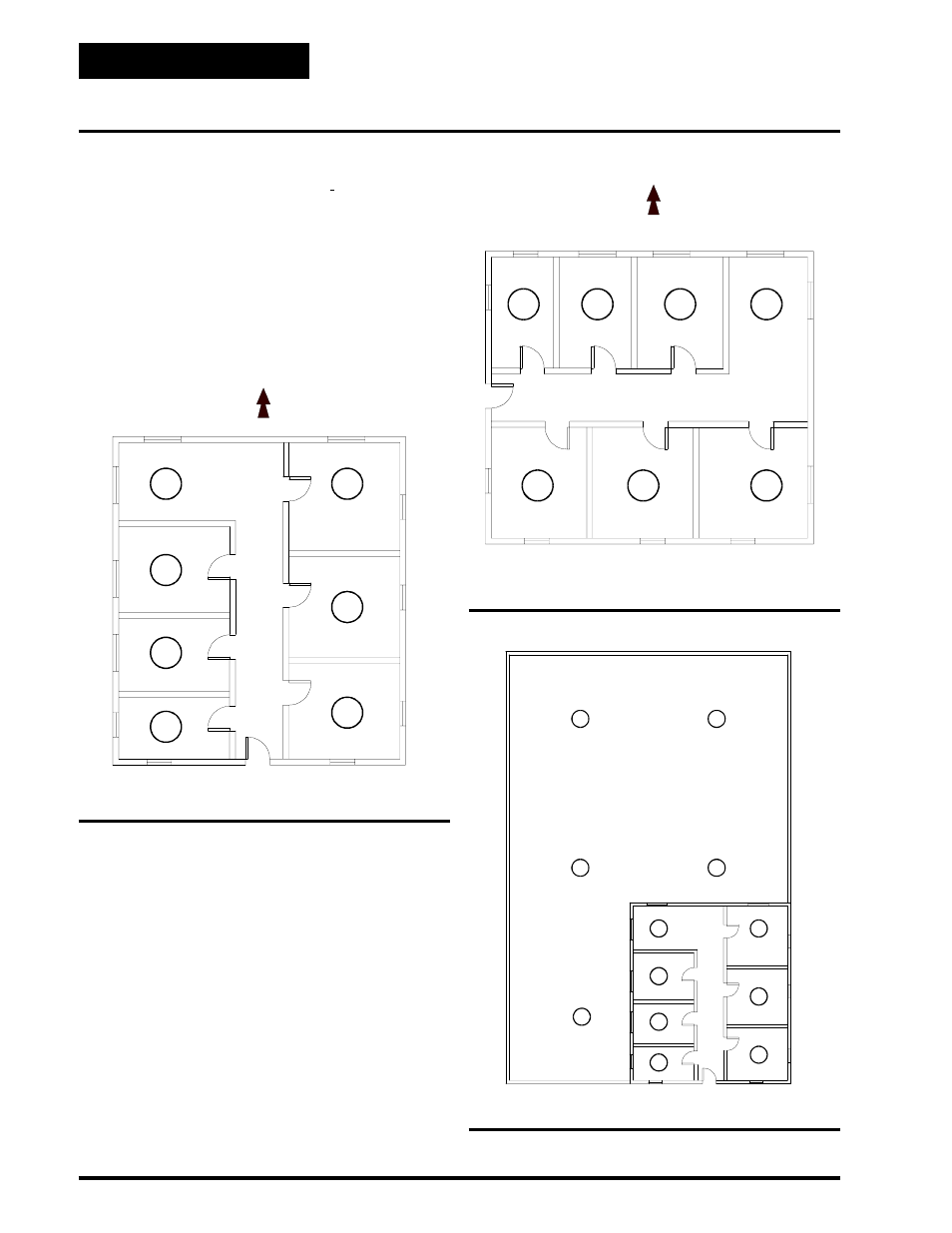
Figure 1-3: Zone Layout With External Zones Only.
Here is another example of the building’s exposure af-
fecting the zoning. Figure 1-3 below shows a building
layout with 7 zones, it has 3 zones with an eastern ex-
posure, 4 zones with a western exposure and two each
north and south exposures. This building can be con-
trolled from a single, constant volume air handler. All
of the zones have exterior surfaces and there are no
totally internal zones, so they will have similar load
requirements.
Figure 1-4 shows a building with 7 zones, 4 of the zones
have a north exposure and the other 3 have a south ex-
posure. Since there is a big difference in the affect on
the building between north and south exposures, this
situation should use two zoned HVAC units.
Figure 1-5 shows a combination manufacturing
facility and office area. The space temperature in the
individual zones numbered 1 through 7, would all be
controlled by a single HVAC unit. A single constant
volume HVAC unit would be used for each of the
zones 8 through 12.
Figure 1-5: Zoning And Constant Volume Units
Figure 1-4: Zones With North And South Exposures.