Auto-zone systems 17 zoning design guide, Step #6 - sizing the zone damper – Auto-Zone Control Systems Zoning Design Guide (Version 01B) User Manual
Page 17
Auto-Zone Systems
17
Zoning Design Guide
Fan
RA Sensor
SA Sensor
Return Air Duct
Supply Air Duct
SP Pickup
Bypass Damper
SP Sensor
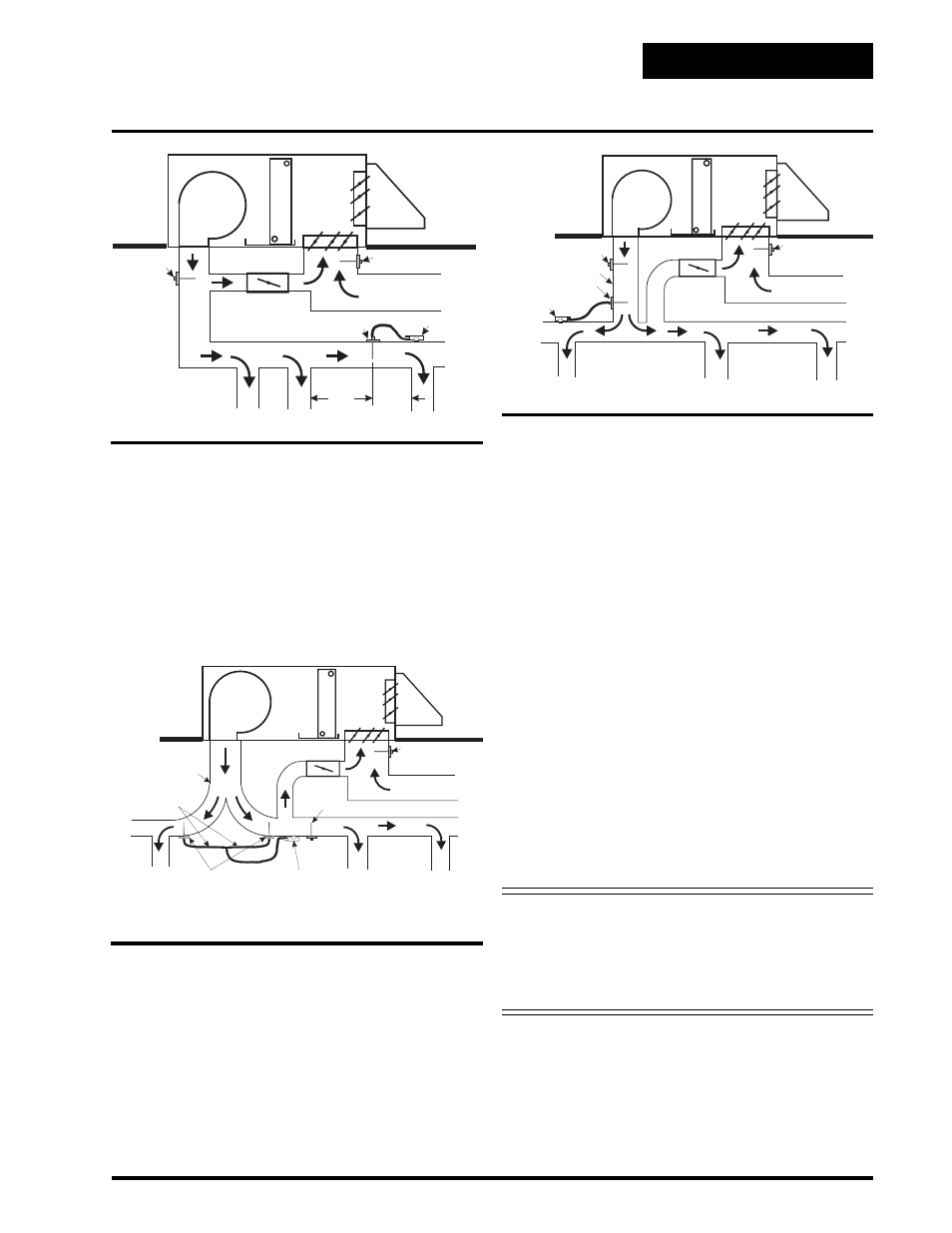
Figure 1-10: Least Desirable Sensor Location
If the supply duct comes directly from the unit and im-
mediately splits in opposite directions, the pressure
pickup should be located ahead of the split, or as close
to it as possible, even if the bypass damper(s) are lo-
cated downstream of the split.
Step #6 - Sizing the Zone Damper
Use a load program to determine the peak load for each
zone. These calculations will be used in selecting the
appropriate zone damper sizes.
Using the maximum acceptable velocity for a branch
duct (typically 1000-1500 FPM for minimal noise), find
the smallest damper that will deliver the required CFM
as determined by the load program.
Locate the branch velocity used in the duct design pro-
gram on the left hand column of the damper sizing chart
(Table 1-1). Move across the chart and find the damper
which will provide the acceptable CFM to meet your
specific zone requirements.
Note
Compare the damper size selected against
the duct size to determine if the next size
up or down will provide acceptable
performance without requiring a transi-
tion fitting.
One additional damper may be slaved together for large
zones. See zone wiring diagram for details. This should
be reserved for situations when it is not practical to use
a single large damper. Round zone dampers can be speci-
fied to be either pressure dependent or independent.
Fan
RA Sensor
SA Sensor
3D
Min.
2D
Min.
Return Air Duct
Supply
A
ir
Duct
SP Pickup
Bypass Damper
SP Sensor
Fan
RA Sensor
SA Sensor
Return Air Duct
Supply Air Duct
Tubing To Be Equal
Length And Size
Bypass Damper
SP Sensor
SP Pickups
If the trunk ducts are properly sized for minimum pres-
sure drop, the location of the static pickup probe is not
particularly critical. It should ideally be located at right
angles to the airflow in a straight section of the supply
duct approximately 2/3 the distance of the total length
of the supply duct. Also the probe should be located
not less than 3 duct diameters downstream and 2 duct
diameters upstream of any elbow or takeoff. See Fig-
ure 1-8.
Figure 1-8: Preferred Sensor Location
Figure 1-9: Acceptable Sensor Location
Since the “ideal” location is often difficult to find in an
installation, a location in the main trunk where the tip
is not in a “negative pressure area” (e.g. just downstream
of the inside curve of an elbow) or an area where the
tube opening is directly impacted by the velocity of the
supply air. See Figure 1-9.