Dvs-36 & dvs-42 framing and finishing (continued), Horizontal termination (for all models) – DVS -30-2 User Manual
Page 22
Page 22
13369-1-0203
DVS-36 & DVS-42 FRAMING AND FINISHING (continued)
Cut a 10-1/2 inch x 10-1/2 inch hole through the ceiling, using the
center point previously marked. Frame the hole with framing
lumber the same size as the ceiling joists. (See Figure 36) If the
area above the ceiling is NOT an attic, position and secure the
ceiling firestop (SD-1263) on the ceiling side of the previously
cut and framed hole. (See Figure 37) If the area above the ceiling
is an attic, position and secure the firestop on top of the previously
framed hole. (See Figure 38)
NOTE: Remove insulation from the framed area in the attic
before installing the firestop and/or vent pipe.
CEILING FIRESTOP
CEILING FIRESTOP
10 1/2"
10 1/2"
267mm
10 1/2"
10 1/2"
267mm
267mm
NAILS, 4 REQUIRED
NAILS, 4 REQUIRED
Figure 38
HORIZONTAL TERMINATION (For All Models)
NOTE: Termination cap should pass through the wall firestop
from the exterior of the building. Adjust the termination
cap to its final exterior position on the building.
WARNING: Termination cap must be positioned so that
arrow is pointing up.
Attach the termination cap with the four wood screws provided.
Before attachment of the termination, run a bead of silicone
sealant rated above 250
°
F on its outside edge too, so as to make
a seal to the exterior wall.
NOTE: Wood screws can and should be replaced with appropriate
fasteners for use on stucco, brick, concrete or other types
of siding.
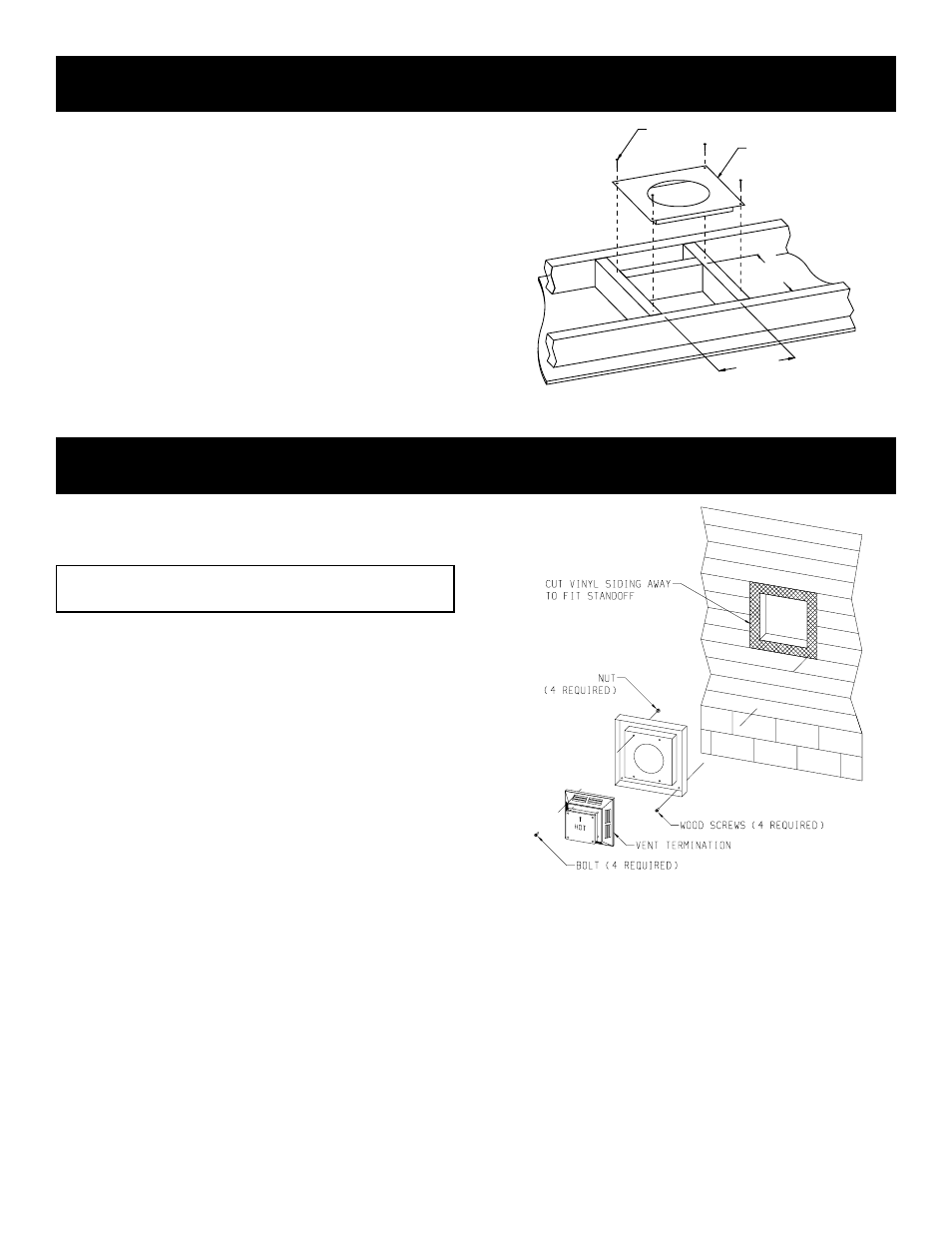
CAUTION: If exterior walls are finished with vinyl siding, it is
necessary to install the vinyl siding standoff SD-950 for DVS-30
or SD-1250 for DVS-36/42.
Vinyl siding standoff SD-950 for DVS-30 or SD-1250 for DVS-
36/42 will be installed between the vent termination and the
exterior wall. (See Figure 39) This horizontal vent termination
bolts onto the flat portion of the vinyl siding standoff, so an air
space will exist between the wall and the termination cap.
Figure 39