ARRIS DCT5100 Installation Manual User Manual
Page 42
4-2
Diagnostics
DCT5100 Installation Manual
Table 4-1 illustrates the OSD of the diagnostic main menu. Note, d13 INTERACTIVE INFO will
only be displayed when Thin Client is running in the DCT5100.
Table 4-1
Main menu - OSD
DIAGNOSTICS
d01
GENERAL
STATUS
d02
PURCHASE
STATUS
d03
OOB STATUS
d04
IN BAND STATUS
d05
UNIT ADDRESS
d06
CURRENT CHANNEL STATUS
d07
UPSTREAM
MODEM
d08
CODE MODULES
d09
MEMORY CONFIG
d10
KEYPAD/LED
d11
INTERFACE
STATUS
d12
USER SETTING STATUS
d13
INTERACTIVE INFO
E
EXIT
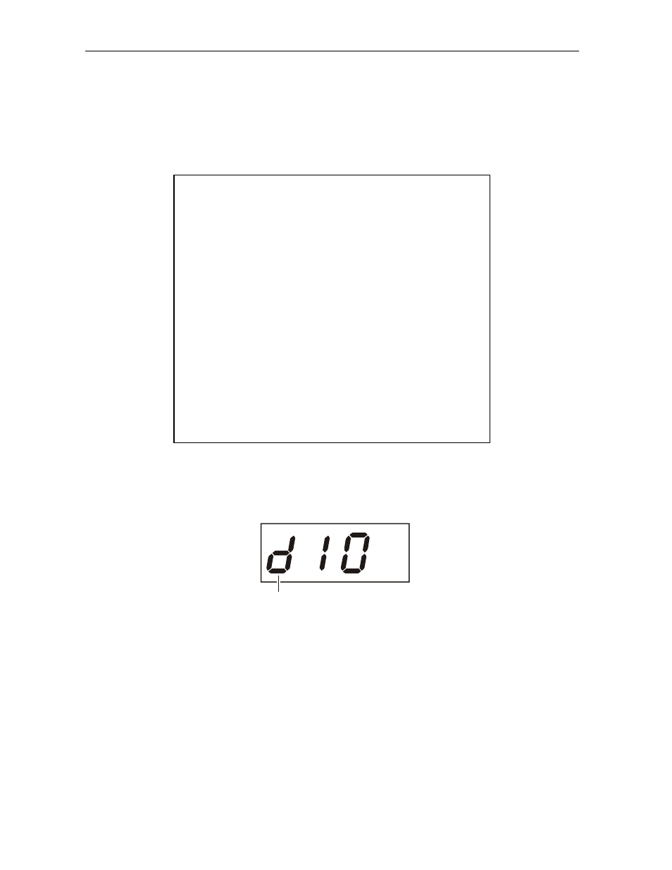
Figure 4-1 is an example of the LED for the main menu selected diagnostic:
Figure 4-1
Main menu diagnostic - LED
MUTE
Selected
diagnostic
from
main menu
MUTE
P