Rear panel, Table 2-2 describes the rear-panel connections, Key item function – ARRIS DCT5100 Installation Manual User Manual
Page 19: Dct5100 installation manual, Table 2-2 rear panel, Ethernet 10base-t port supports pc networking. 4, Connector
Overview 2-3
DCT5100 Installation Manual
Rear Panel
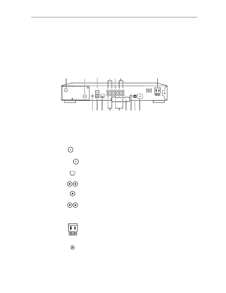
Figure 2-2 illustrates the rear panel of the DCT5100, which contains a switched power outlet;
connectors for video, audio, and RF cabling; data output; and modem and data interface
connectors.
Figure 2-2
DCT5100 rear panel
ETHERNET
USB
HPNA
AUDIO IN
AUDIO
OUT
VIDEO
IR
R
IN
R
L
OUT
S-VIDEO
IEEE 1394
OPTICAL
SPDIF
SPDIF
L
Y
Pb
Pr
TV
Pass Card
SWITCHED
105-125V
60Hz
4A MAX
500W MAX
CONVENIENCE
OUTLET
TO
TV/VCR
CABLE
IN
1
2
4
5 6
7
8 9 10
11
12 13 14
16
15
3
Table 2-2 describes the rear-panel connections:
Table 2-2
Rear panel
Key Item
Function
1
TO
TV/VCR
F-type connector used to connect the DCT5100 to a standard
TV or VCR operating on channel 3 or 4.
2
CABLE
IN
F-type connector used for the coaxial cable input from service
provider (input to integrated RF return).
3
ETHERNET
Ethernet 10Base-T port supports PC networking.
4
AUDIO IN
R
L
RCA jacks for loop-through audio from audio equipment.
5
SPDIF
The
SPDIF
connector
is a digital output connection that carries
Dolby Digital 5.1 audio or PCM audio.
6
VIDEO
IN
OUT
VIDEO IN
– RCA jack connects the DCT5100 to a composite
(baseband) video input from a TV, VCR, camcorder, or other
video device.
VIDEO
OUT
– RCA jack that delivers video to an external device
such as a VCR or TV.
7
CONVENIENCE
OUTLET
AC power outlet that can be configured as a switched or
unswitched outlet; and a two-pronged plug for attaching a
power cord.
8
IR
Miniphono jack enabling the DCT5100 to control a VCR using
an optional low power IR Blaster transmitter (not all electronic
program guides support this feature).