Buz1: onboard buzzer, Sata_p1, Sata1 – Aplex Technology ACS-2210A User Manual
Page 19: Mpcie1, H1/h2
ACS-2210A User Manual
19
sure that the connector pins have a one-to-one correspondence with
chassis wiring, or it may cause boot up failure.
16. BUZ1: onboard buzzer.
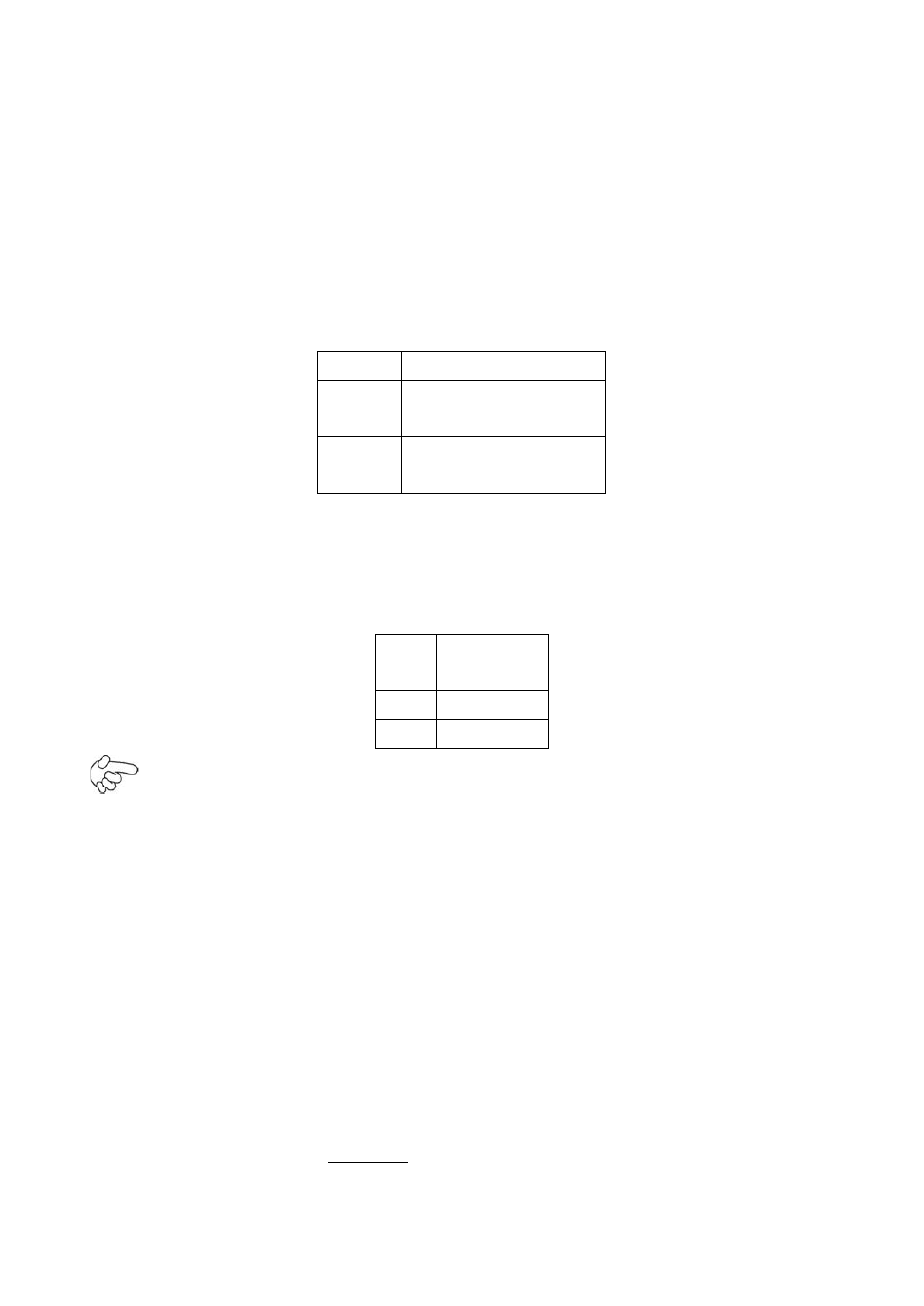
17. JP2:
(2.0mm Pitch 2x2 Pin Header), mSATA/SATA1 Devices Master or slave
jumper setting. While using mSATA/SATA1 devices at the same time, one of the
devices must be set as Master.
JP2
Devices Master
1~2 on
3~4 off
mSATA Master
1~2 off
3~4 on
SATA1 Master
18. SATA_P1:
(2.5mm Pitch 1x2 box Pin Header),an onboard 5V output
connector is reserved to provide power for SATA devices.
Pin#
Signal
Name
1
+DC5V
2
Ground
Note:
Output current of the connector must not be above 1A.
19. SATA1:
(SATA 7P),,
SATA Connectors, one SATA connectors are provided, with
transfer speed up to 3.0Gb/s.
20. MPCIE1
: (50.95mmx30mm Socket 52Pin),mini PCIE socket, it is located at the
top, it supports mini PCI-E devices with USB2.0, SMBUS and PCI-E signal.
21. H1/H2
:
MPCIE1 SCREW HOLES, H1 for
mini PCIE card (50.95mmx30mm Socket 52
Pin) assemble.
H2 Reserve.