Aplex Technology ACS-2210A User Manual
Page 18
ACS-2210A User Manual
18
5V_S0
49
50
5V_S0
RS232
(COM4)
RS232
(COM4)
DSR4-
51
52
DCD4-
RTS4-
53
54
RXD4
CTS4-
55
56
TXD4
RI4-
57
58
DTR4-
Ground
59
60
Ground
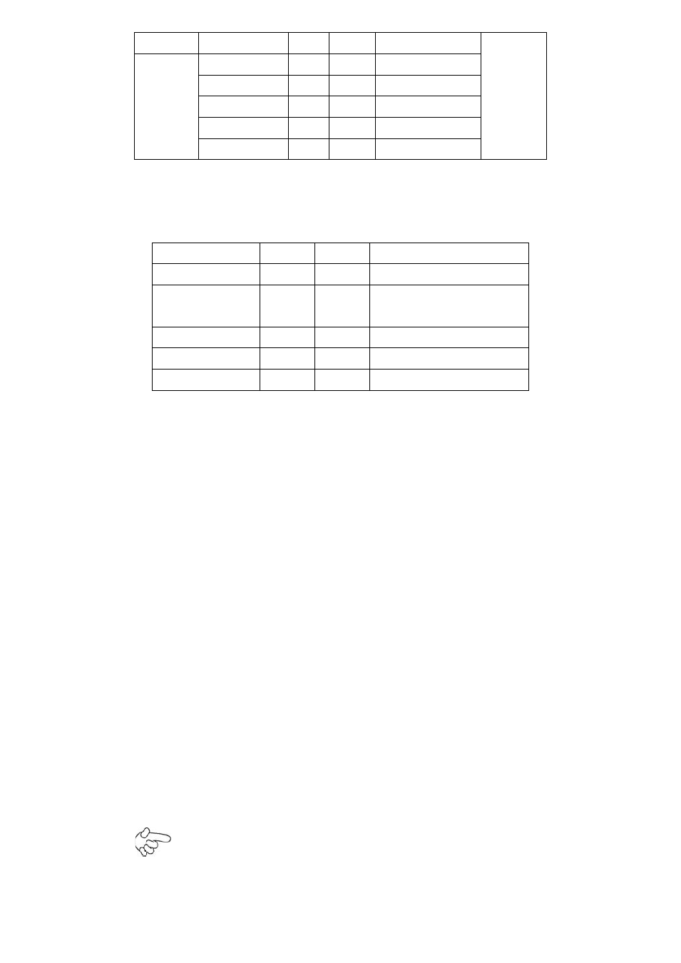
15. FP1:
(2.0mm Pitch 2X5 Pin Header), Front panel connector.
Signal Name
Pin#
Pin#
Signal Name
HD LED+
1
2
POWER LED+
HD LED-
3
4
POWER LED-
(Ground)
Ground
5
6
PWR_ON
RESET+
7
8
Ground
WAN LED-
9
10
WAN LED+
Pin1-3:
HDD LED, They are used to connect hard disk activity LED. The LED blinks when the
hard disk is reading or writing data.
Pin2-4:
POWER LED, They are used to connect power LED. When the system is powered on
or
under S0/S1 state, the LED is normally on; when the system is under S4/S5 state, the
LED is off.
Pin5-6:
POWER on/off Button, They are used to connect power switch button. The two pins
are
disconnected under normal condition. You may short them temporarily to realize
system
startup & shutdown or awaken the system from sleep state.
Pin7-8:
RESET Button, They are used to connect reset button. The two pins are
dis-connected
under normal condition. You may short them temporarily to realize system reset.
Pin9-10:
WAN LED, They are used to connect WAN LED.
Note:
When connecting LEDs, pay special attention to the signal polarity. Make