Aplex Technology ARCHMI-807 User Manual
Page 59
ARCHMI-8XX Series User Manual
58
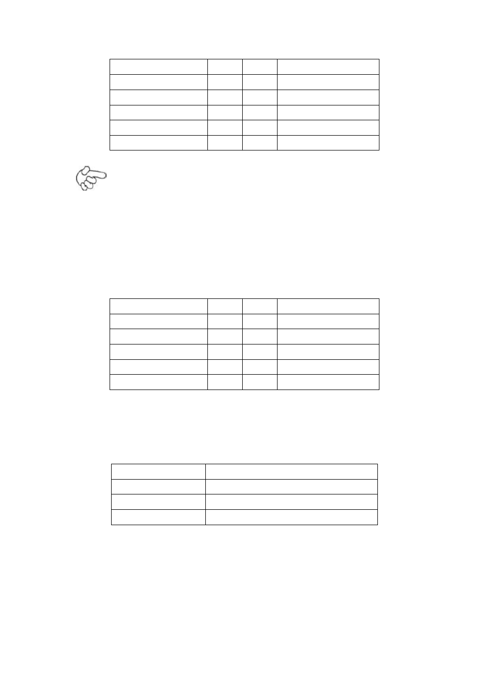
Signal Name
Pin#
Pin#
Signal Name
5V_USB23
1
2
5V_USB23
NC (USB3_N)
3
4
NC (USB2_N)
NC (USB3_P)
5
6
NC (USB2_P)
Ground
7
8
Ground
NC
9
10
Ground
Note:
Before connection, make sure that pinout of the USB Cable is in accordance
with that of the said tables. Any inconformity may cause system down and
even hardware damages.
JP_SET(option):
(2.0mm Pitch 2x5 Pin Header).
Signal Name
Pin#
Pin#
Signal Name
3P3V_S5_USB
1
2
3P3V_S5
3P3V_S5_USB
3
4
3P3V_S5
3P3V_S5_USB
5
6
3P3V_S5
PSON_ATX
7
8
Ground
PSON_ATX
9
10
Ground
JP6:
(2.0mm Pitch 2x3 Pin Header), COM4 setting jumper, pin 1~6 are used to select
signal out of pin 9 of COM4 port.
JP6 Pin#
Function
Close 1-2
RI (Ring Indicator) (default)
Close 3-4
COM4 Pin9=+5V (option)
Close 5-6
COM4 Pin9=+12V (option)
COM4:
(2.0mm Pitch 2X5 Pin Header), COM4 Port, up to one standard RS232 port are
provided. They can be used directly via COM cable connection.