Aplex Technology ARCHMI-707 User Manual
Page 53
51
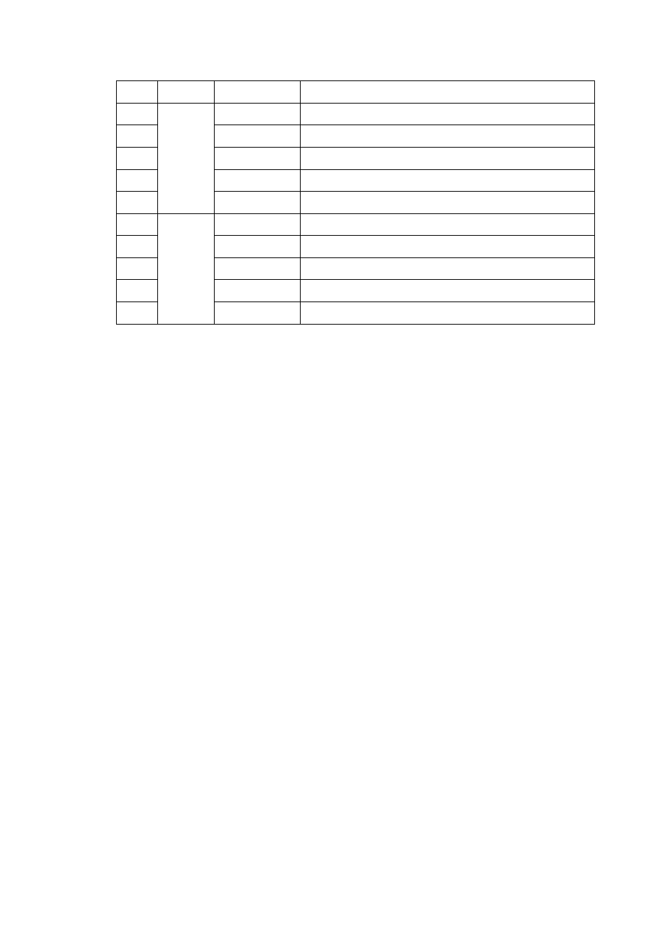
Pin#
Channel
Signal Name
Function
1
CAN2
CANL2
CAN bus Signal L
2
R2-
Terminal resistor R-(internally connected to CANL2)
3
FG
Shield cable (FG)
4
R2+
Terminal resistor R+( internally connected to CANH2)
5
CANH2
CAN bus Signal H
6
CAN1
CANL1
CAN bus Signal L
7
R1-
Terminal resistor R-(internally connected to CANL1)
8
FG
Shield cable (FG)
9
R1+
Terminal resistor R+( internally connected to CANH1)
10
CANH1
CAN bus Signal H
【See TB-528AN2 Manual】
This manual is related to the following products: