Aplex Technology ARCHMI-707 User Manual
Page 37
35
LA_CLKP
22
21
LA_CLKN
Ground
24
23
Ground
Ground
26
25
Ground
USB1
USB1_P
28
27
USB1_N
USB1
USB0
USB0_P
30
29
USB0_N
USB0
5V_USB01
32
31
5V_USB01
USB1
5V_USB01
34
33
5V_USB01
PWR LED
PWR_LED+
36
35
HDD_LED+
HDD LED
Ground
38
37
Ground
PWR ON/OFF
PWRBTN_ON-
40
39
FP_RST-
RESET
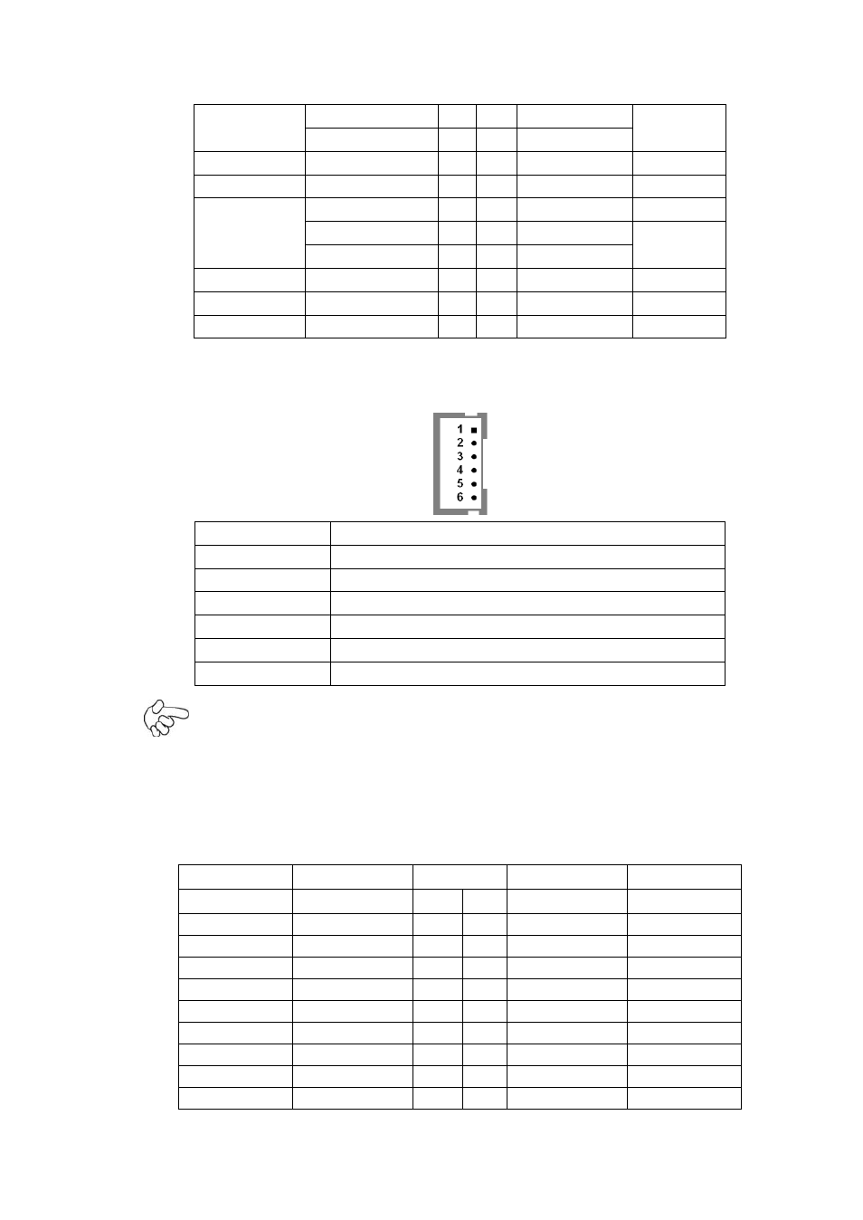
INVT1:
(2.0mm Pitch 1x6 Pin wafer connector), Backlight control connector for LVDS.
Pin#
Signal Name
1
+DC12V
2
+DC12V
3
Ground
4
Ground
5
BKLT_EN_OUT
6
BKLT_CTRL
Note:
Pin6 is backlight control signal, support DC or PWM mode, mode select at BIOS CMOS menu.
30. CN2:
(DF13-20P Connector), for expand output connector, it provides eight GPIO, one RS422 or RS485.
Function
Signal Name
Pin#
Signal Name
Function
5V
5V_S5
2
1
5V_S5
5V
SIO_GPIO61
GPIO_IN2
4
3
GPIO_IN1
SIO_GPIO60
SIO_GPIO63
GPIO_IN4
6
5
GPIO_IN3
SIO_GPIO62
Ground
8
7
Ground
SIO_GPIO21
GPIO_OUT2
10
9
GPIO_OUT1
SIO_GPIO20
SIO_GPIO23
GPIO_OUT4
12
11
GPIO_OUT3
SIO_GPIO22
Ground
14
13
Ground
485 or 422
485+_422TX+
16
15
485-_422TX-
485 or 422
RS422
422_RX+
18
17
422_RX-
RS422
5V
5V_S0
20
19
5V_S0
5V