Com5, Com2/com4 – Aplex Technology APC-3591A User Manual
Page 15
APC-3X91A User Manual
15
Note:
When connecting LEDs and buzzer, pay special attention to the signal
pola-
rity. Make sure that the connector pins have a one-to-one correspondence
with chassis wiring, or it may cause boot up failure.
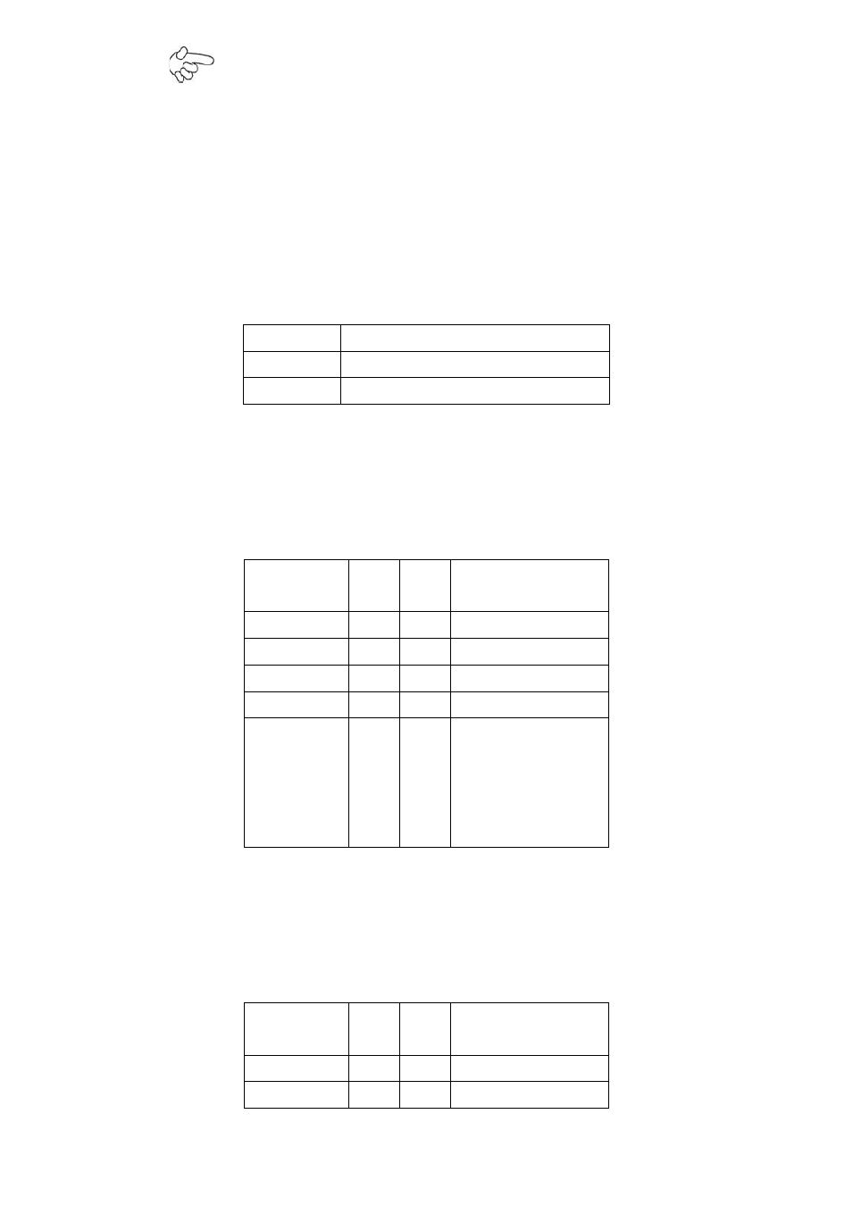
5. JP1:
(2.0mm Pitch 1x3 Pin Header) COM5 setting jumper, pin 1~3 are used to
select signal out of pin 10 of COM5 port.
JP1 Pin#
Function
Close 1-2 COM5 Pin10=+5V (default)
Close 2-3
COM5 Pin10=+12V (option)
6. COM5
: (2.0mm Pitch 2X5 Pin Header), COM5 Port, standard RS232 ports are
provided. They can be used directly via COM cable connection.
Signal
Name
Pin# Pin# Signal Name
DCD
1
2
RXD
TXD
3
4
DTR
Ground
5
6
DSR
RTS
7
8
CTS
RI
9
10
Jp1 Setting:
Pin1-2 : 5V
(default)
Pin2-3:12V
(option)
7. COM2/COM4
: (2.0mm Pitch 2X5 Pin Header),COM2 COM4 Port, up to 2
standard RS232 ports are provided. They can be used directly via COM cable
connection.
Signal
Name
Pin# Pin# Signal Name
DCD
1
2
RXD
TXD
3
4
DTR