Bat1, F_panel – Aplex Technology APC-3591A User Manual
Page 14
APC-3X91A User Manual
14
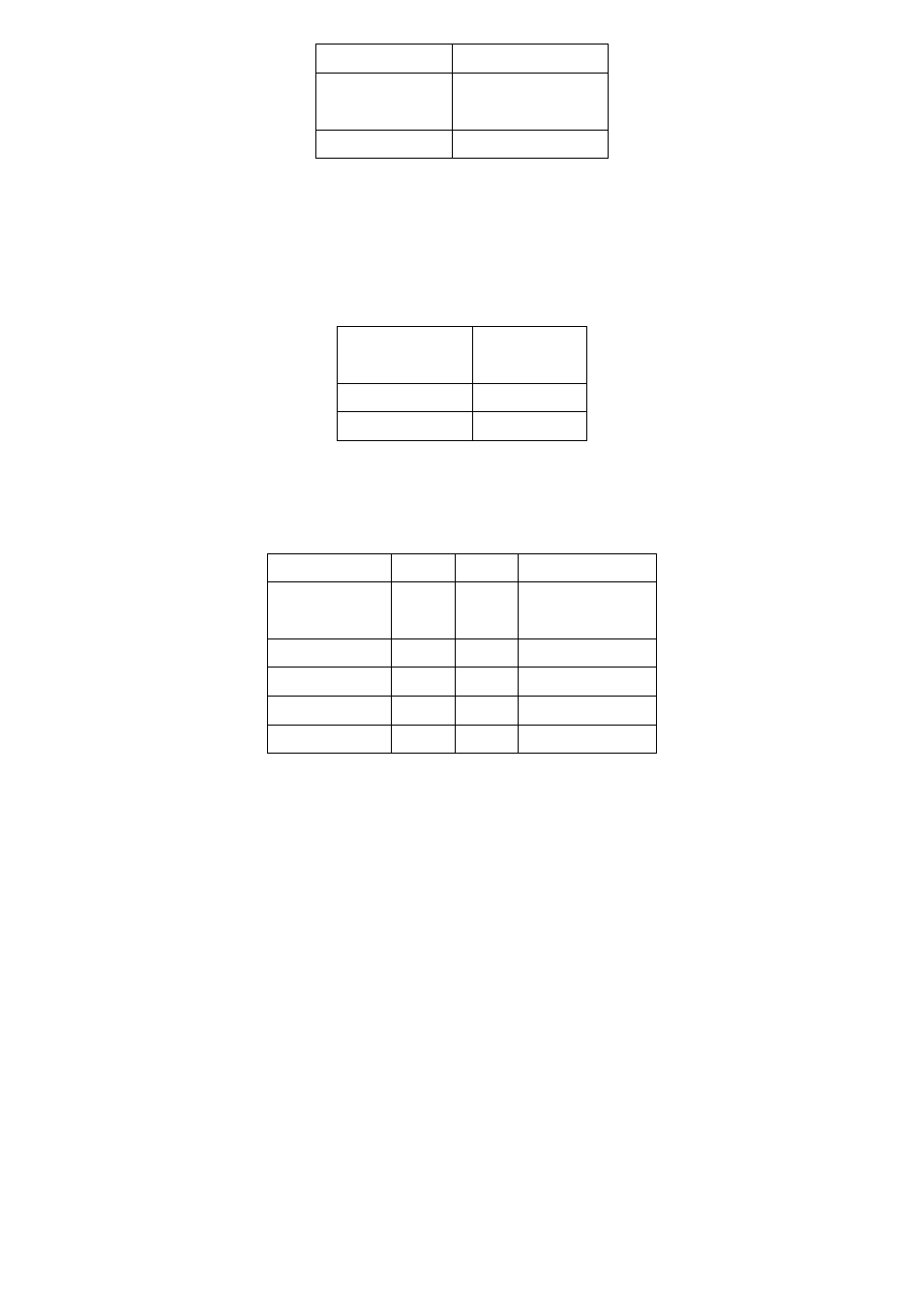
JP2
Mode
Open
ATX Power
Mode
Close
Auto Power on
3. BAT1:
(1.25mm Pitch 1X2 box Pin Header) 3.0V Li battery is embedded to
provide power for CMOS.
Pin#
Signal
Name
Pin1
VBAT
PIN2
Ground
4. F_PANEL:
(2.0mm Pitch 2X5 Pin Header), Front panel connector.
Signal Name Pin#
Pin# Signal Name
HD LED+
1
2
POWER
LED+
Ground
3
4
Ground
Ground
5
6
SW+
RESET+
7
8
Ground
SPK+
9
10
SPK-
Pin1-3: HDD LED, They are used to connect hard disk activity LED. The LED blinks
when the hard disk is reading or writing data.
Pin2-4: POWER LED, They are used to connect power LED. When the system is
powered on or under S0/S1 state, the LED is normally on; when the
system is under S4/S5 state, the LED is off.
Pin5-6: POWER on/off Button, They are used to connect power switch button.
The two pins are disconnected under normal condition. You may short
them temporarily to realize system startup & shutdown or awaken the
system from sleep state.
Pin7-8: RESET Button, They are used to connect reset button. The two pins are
dis-
connected under normal condition. You may short them temporarily to
realize
system reset.
Pin9-10: BUZZER, They are used to connect an external buzzer.