AMETEK MX Series Installation Manual User Manual
Page 29
Installation Manual - Rev D
California Instruments
MX Series
25
BNC
Description
1
Trigger Input (TTL input)
2
Trigger Output (TTL output) (Same signal connection as Function Strobe. Some units
may not have this output connected. If you don’t get an output trigger on this BNC, use
the Function Strobe BNC instead.)
3
Function Strobe (TTL output) (Same signal connection as Trigger Output)
4
Clock (TTL output on Master / TTL input on Auxiliary)
5
Lock (TTL output on Master / TTL input on Auxiliary)
6
Emergency Shut off inter connect. Installed only on
–MB systems with –ES
Option.
2.7.4 External Sense Connector
Table 2-7: External Sense Connector
Pin
Description
1
Phase A sense
2
Phase B sense
3
Phase C sense
4
Neutral sense
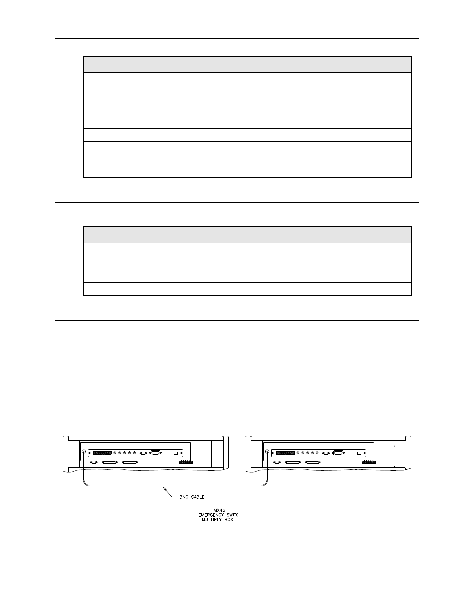
2.7.5 ES Option - Emergency Switch Interconnect for
–MB systems – BNC
An optional BNC connector is located on the rear panel for connecting multiple chassis, each
having a controller and an emergency shut off switch (-ES option). This connection is required to
create an OR-ed operation of more than one
–ES switch.
This connector is only present on MX-MB systems with the
–ES option. If present, a suitable
BNC cable should be used to connect the emergency shut off signal between chassis. This
connector is labeled as follows:
"Caution: BNC cable must be connected for system Emergency Shut-Down"
See figure below for an illustration of a MX90-MB-ES interconnect.
Figure 2-14: Emergency Switch (ES Option) shut off inter connect on -MB systems.