AMETEK MX Series Installation Manual User Manual
Page 21
Installation Manual - Rev D
California Instruments
MX Series
17
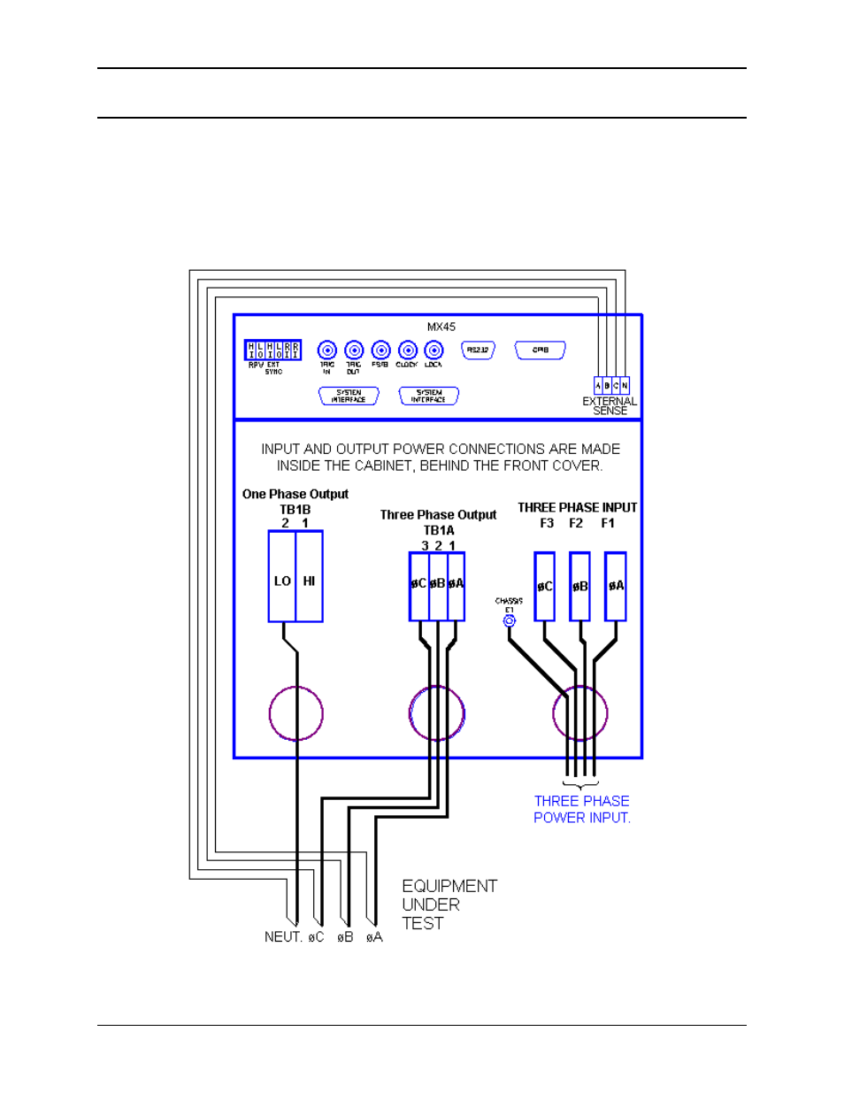
2.6.4 MX45-3 and and MX45-3Pi 3ø mode Output Wiring Diagram
Figure 2-8 shows the required output connections for a MX45-3 three phase or a MX45-3Pi in
three phase mode output configuration (rear-view perspective). See section 2.6.2 for the MX45-
3Pi in single-phase mode.
Always disconnect all input power from the MX45 before removing the front panel cover that
provides access to the input and output terminal connections. Route the wires from the back of
the MX45 to the front in the provided cable guides.
Figure 2-8: MX45-3 Output Wiring
See also other documents in the category AMETEK Equipment:
- CW-M (48 pages)
- CW-M Corrected Table 4-2 in (1 page)
- CW-P (62 pages)
- Lx Series (205 pages)
- CW Series Programming Manual (25 pages)
- Ls Series II Programming Manual (242 pages)
- Compact i/iX Series (157 pages)
- Compact IX 2253 (157 pages)
- Compact i/iX Series Software Manual (203 pages)
- ASD Series Quick Start (5 pages)
- ASD Series (120 pages)
- i-iX Series II Programming Manual (226 pages)
- DLM 600W Series Programming Manual (24 pages)
- M131 Programming Manual (99 pages)
- DLM Series (74 pages)
- DLM 600W Series (82 pages)
- BPS Series (153 pages)
- DLM600 Series (16 pages)
- DLM-E 4kW Series Programming Manual (32 pages)
- DCS-E 1.2kW Series (65 pages)
- M136 (8 pages)
- DCS-E 3kW Series (94 pages)
- CTS 3.0 (166 pages)
- CSW Series (174 pages)
- 2003RP (126 pages)
- 2001RP (131 pages)
- MX CTSH (151 pages)
- MXCTSL Administrator Manual (27 pages)
- MX CTSL (157 pages)
- RS Series (228 pages)
- Ls AC source (2 pages)
- MX15 Series (184 pages)
- Ls Series II (226 pages)
- Lx Series Driver Manual (275 pages)
- MX Series Rev: AY (257 pages)
- iX Series (341 pages)
- i-iX Series II (258 pages)
- GUPS 2400A-108 (36 pages)
- HPD Series (58 pages)
- HPD Series Operation Manual (41 pages)
- HPD Series GPIB-Multichannel (134 pages)
- PLA-PLW Programming Manual (74 pages)
- ReFlex Mating Connnectors for Controller (3 pages)
- LPDC-16V (4 pages)