AMETEK MX Series Installation Manual User Manual
Page 24
Installation Manual - Rev D
California Instruments
MX Series
20
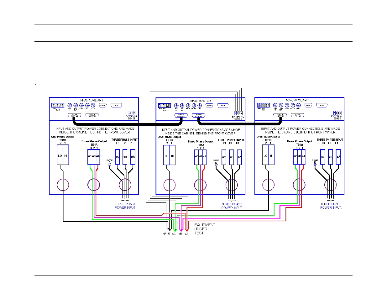
2.6.6 MX135 Output Wiring Diagram
Figure 2-11 shows the required output connections for a MX135-3Pi or MX135-3Pi-MB three phase output configuration (rear-view
perspective). Always disconnect all input power from the MX135 before removing the front panel cover that provides access to the input
and output terminal connections. Route the wires from the back of the MX45 chassis to the front in the provided cable guides. Note that
the master is shown in the center in this drawing. MX90 and MX135 systems are shipped with external output terminal blocks that enable
the output wiring from two or three chassis to be combined, providing a single point of connection to the EUT. These blocks are not
enclosed however.
Figure 2-11: MX135 or MX135-MB Output Wiring
- CW-M (48 pages)
- CW-M Corrected Table 4-2 in (1 page)
- CW-P (62 pages)
- Lx Series (205 pages)
- CW Series Programming Manual (25 pages)
- Ls Series II Programming Manual (242 pages)
- Compact i/iX Series (157 pages)
- Compact IX 2253 (157 pages)
- Compact i/iX Series Software Manual (203 pages)
- ASD Series Quick Start (5 pages)
- ASD Series (120 pages)
- i-iX Series II Programming Manual (226 pages)
- DLM 600W Series Programming Manual (24 pages)
- M131 Programming Manual (99 pages)
- DLM Series (74 pages)
- DLM 600W Series (82 pages)
- BPS Series (153 pages)
- DLM600 Series (16 pages)
- DLM-E 4kW Series Programming Manual (32 pages)
- DCS-E 1.2kW Series (65 pages)
- M136 (8 pages)
- DCS-E 3kW Series (94 pages)
- CTS 3.0 (166 pages)
- CSW Series (174 pages)
- 2003RP (126 pages)
- 2001RP (131 pages)
- MX CTSH (151 pages)
- MXCTSL Administrator Manual (27 pages)
- MX CTSL (157 pages)
- RS Series (228 pages)
- Ls AC source (2 pages)
- MX15 Series (184 pages)
- Ls Series II (226 pages)
- Lx Series Driver Manual (275 pages)
- MX Series Rev: AY (257 pages)
- iX Series (341 pages)
- i-iX Series II (258 pages)
- GUPS 2400A-108 (36 pages)
- HPD Series (58 pages)
- HPD Series Operation Manual (41 pages)
- HPD Series GPIB-Multichannel (134 pages)
- PLA-PLW Programming Manual (74 pages)
- ReFlex Mating Connnectors for Controller (3 pages)
- LPDC-16V (4 pages)