Connecting to a power supply – Zilog Z80195 User Manual
Page 18
Z80185/195 D
EVELOPMENT
K
IT
U
SER
'
S
M
ANUAL
2-10
UM951800100
Z
ILOG
CONNECTING TO A POWER SUPPLY
Connecting to a separate power supply.
If your power supply allows voltage adjustment, do the
following (refer to Figure 2-1):
1. Turn the 2.0A power supply on and adjust it to +5V.
2. Set the +5V power supply for at least 1.5A, if there’s a current-limiting adjustment.
3. Turn the supplies off, or make sure non-adjustable supplies are off.
4. Locate the short power cable (red wire, black wire, and banana plugs on one end).
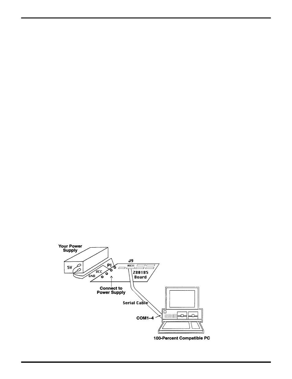
5. Insert one end of the power cable (polarized) into P1 of the board.
6. Plug the black banana plug into the black jack on the power supply connector that’s labeled COM,
GND, or with a ground symbol.
7. Plug the red plugs into the proper red jacks on the power supply (labeled "+" or "+V" or "+5V").
Note:
Some manufacturers will also have black or white jacks. Refer to individual manufacturers'
manuals to decide how to connect in this case.
Using your PC for power supply.
Most PCs have extra power capacity to allow for add-in cards. You
may be able to connect a spare disk-drive power cable to P1, thus eliminating the need for a separate
power supply.
Note:
The board draws less than 1A on +5V and does not use the +12V in the disk-drive cable.
1. Turn the 2.0A power supply on and adjust it to +5V.
2. Set the +5V power supply for at least 1.5A, if there’s a current-limiting adjustment.
3. Turn the supplies off, or make sure non-adjustable supplies are off.
4. Locate the short power cable (red wire, black wire, and banana plugs on one end).
5. Insert one end of the power cable (polarized) into P1 of the board.
Connecting the Serial Cable to the PC.
Locate the serial cable. Connect the male end to the female
connector on the side of the development board, and the female end to either the COM1, COM2,
COM3, or COM4 connector of your PC.
Note:
If connector availability is limited to a 9-pin COM1 through COM4, you’ll have to use either a
different cable or a 25-pin to 9-pin converter. (Zilog does not provide either of these items.)
Figure 2-1. Z80185/195 Development Board-to-PC Hook-Up Diagram