Configure the hardware – Zilog EZ80190 User Manual
Page 2
ZDI232ZPAK2ZPK
ZiLOG ZPAK II Debug Interface Module
Page 2
UM016301-1003
Configure the Hardware
1. Set up the target development kit as described in its quick start guide (supplied on the
CD-ROM).
2. Connect the Target Interface Module (TIM) to the ZPAK II module using the keyed
40-conductor ribbon cable.
3. Connect the TIM to the ZDI port on the target development board. Align pin 1 of the
TIM to pin 1 of the development board’s ZDI socket.
5. If using an Ethernet hub, connect an Ethernet patch cable from a free port on the
Ethernet hub to the Ethernet port on the ZPAK II module. Connect the PC’s Ethernet
port to the same hub.
If connecting the development PC directly to the ZPAK II module, connect a cross-
over Ethernet cable from the PC to the ZPAK II module.
6. Connect the serial COM port on the PC to the console port on the ZPAK II module via
the supplied serial cable and the 10-pin adapter cable. (You may need to reconfigure
the ZPAK II module IP address for your networking environment.)
7. Connect the 5 VDC power supply to the ZPAK II module.
Configure the Hardware
The default IP address and subnet mask of the ZPAK II module are 192.168.1.50 and
255.255.255.0, respectively. To enable communication between the PC and the ZPAK II
module, you must either change the PC’s Ethernet settings to match those of the module or
vice versa.
If using the PC in a non-networked configuration, set the PC’s IP address to 192.168.1.21
and its subnet mask to 255.255.255.0. See “"Changing the PC’s Settings to Match the
ZPAK II Module"” on page 3 for instructions.
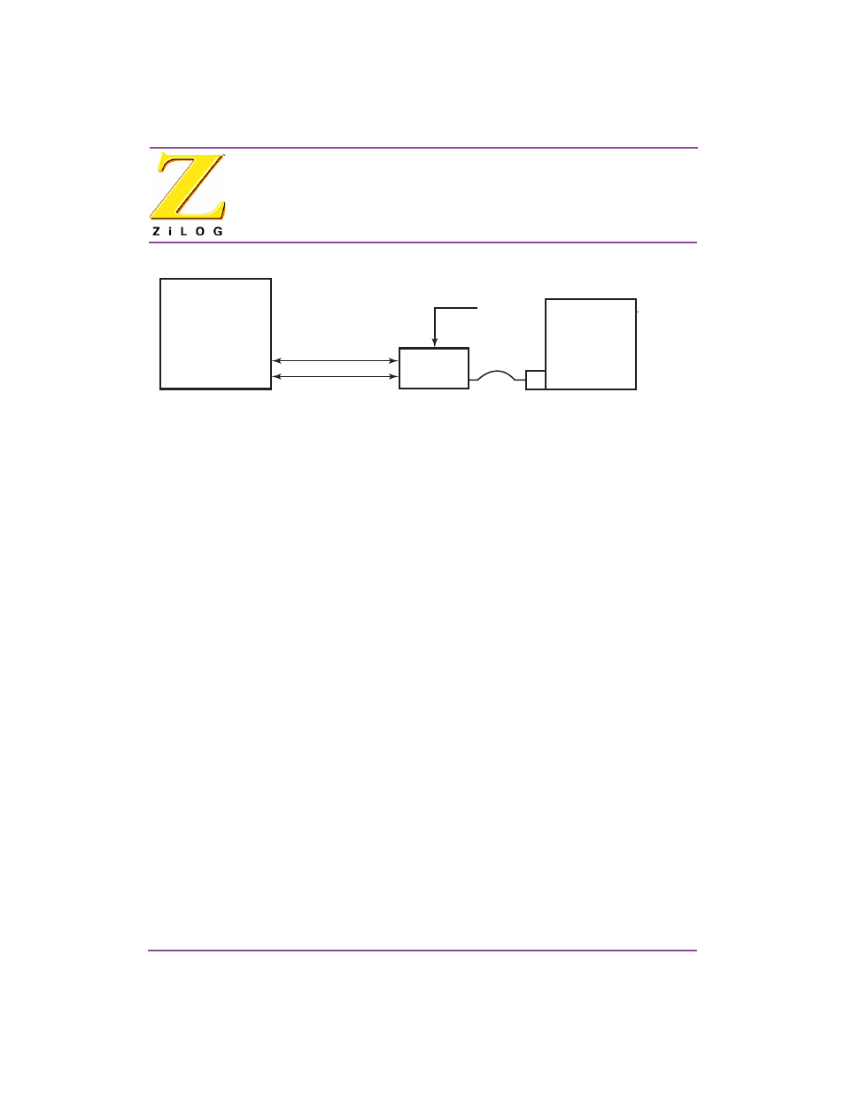
Figure 2. Hardware Setup using a Crossover Ethernet Cable
ZPAK II
Development PC
eZ80
Development
Platform
eZ80
Module
ZDI
TIM
5 VDC
9 VDC
Crossover CAT5
RS-232
¤
¤
eZ80
Development
Module
Development
Kit