Zilog Z51F6412 User Manual
Page 24
UM025901-1112
Configure the Z8051 OCD and Z51F6412 Development
Z51F6412 Development Kit
User Manual
17
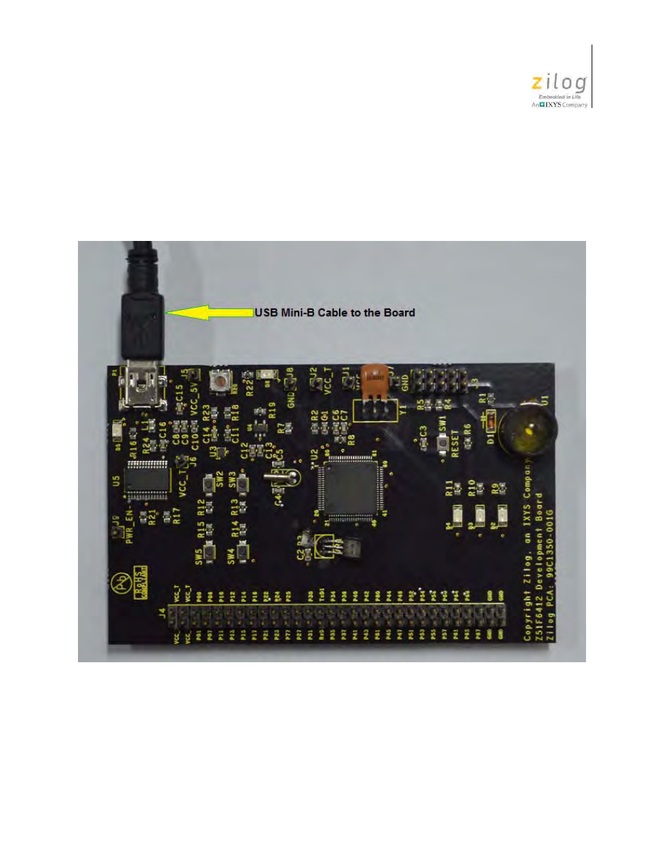
4. Using the second USB-to-Mini-B cable, connect the standard USB end to the host
PC’s USB port.
5. Connect the other end of this second Mini-B cable to the Z51F6412 Board’s P1 con-
nector to apply power to the Board. Note that the green LED D5 is ON; see Figure 14.
Figure 15 shows an example of a completed hardware and software setup.
Figure 14. Connecting the USB Mini-B Cable to the Board
This manual is related to the following products:
See also other documents in the category Zilog Sensors:
- S3F94C8 (11 pages)
- S3F80QB (29 pages)
- S3F8S19 (38 pages)
- Z51F6412 (55 pages)
- Z51F6412 (96 pages)
- EZ80F93 (11 pages)
- Z16F6411 (20 pages)
- Z16F6411 (216 pages)
- EZ80F93 (13 pages)
- ZMOT0BSB (314 pages)
- ZMOT0BSB (582 pages)
- Z8F083A (14 pages)
- Z8F082A (18 pages)
- Z8F2480 (17 pages)
- Z8F082A (15 pages)
- Z8F0822 (17 pages)
- Z8F6423 (83 pages)
- Z8F2480 (18 pages)
- Z8F2480 (19 pages)
- Z8F6423 (18 pages)
- Z8F6423 (27 pages)
- Z8F6482 (50 pages)
- EZ80L92 (26 pages)
- EZ80L92 (79 pages)
- EZ80F91GA (469 pages)
- EZ80F915 (411 pages)
- EZ80F91NAA (34 pages)
- EZ80F91 (41 pages)
- EZ80L92 (40 pages)
- EZ80L92 (10 pages)
- eZ80F92 (87 pages)
- Z16FMC6 (41 pages)
- ZUSBOPTS (38 pages)
- ZUSBOPTS (59 pages)
- Z16FMC6 (520 pages)
- Z8FMC16 (26 pages)
- Z16FMC6 (8 pages)
- Z16FMC6 (26 pages)
- ZMOT1AHH (25 pages)
- ZMOT0BSB (34 pages)
- EZ80F915 (78 pages)
- EZ80190 (87 pages)
- EZ80L92 (86 pages)
- EZ80F91GA (127 pages)