Delta 36-650 User Manual
Page 26
26
For certain cutting operations such as
dadoing and moulding where you are not cutting
completely through the workpiece, the blade guard and
splitter assembly cannot be used. Loosen screws (G) and
(H) Fig. 85. Lift up and swing blade guard and splitter
assembly (W) Fig. 86, to the rear of the saw, and then
tighten screws (G) and (H).
Always return and fasten the blade guard
and splitter assembly to its proper operating position for
normal thru-sawing operations.
The moulding cutterhead (A) Fig. 87, is assembled to the
saw arbor as shown.
THE OUTSIDE ARBOR FLANGE CAN
NOT BE USED WITH THE MOULDING CUTTERHEAD,
TIGHTEN THE ARBOR NUT AGAINST THE
CUTTERHEAD BODY. DO NOT LOOSE THE OUTSIDE
ARBOR FLANGE, FOR IT WILL BE NEEDED WHEN
REATTACHING A BLADE TO THE SAW ARBOR. ALSO,
THE ACCESSORY MOULDING CUTTERHEAD TABLE
INSERT (B), MUST BE USED IN PLACE OF THE
STANDARD TABLE INSERT.
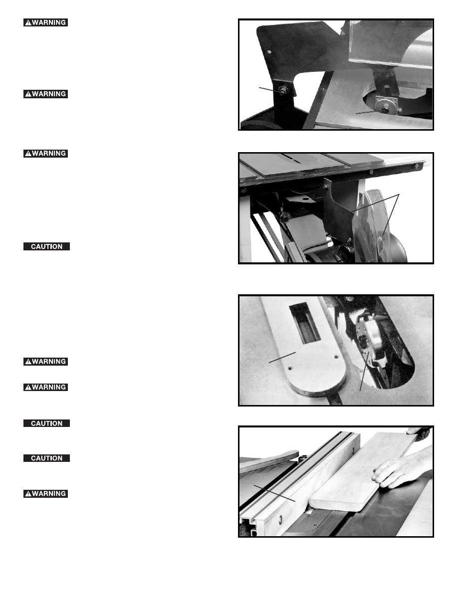
It is necessary when using the moulding
cutterhead to add wood-facing (C) to the face of the rip
fence, as shown in Fig. 88. The wood-facing is attached
to the fence with fasteners, as shown. 3/4 inch stock is
suitable for most work although an occasional job may
require 1 inch facing.
Position the wood-facing over the cutterhead with the
cutterhead below the surface of the table. Turn the saw
on and raise the cutterhead. The cutterhead will cut its
own groove in the wood-facing. Fig. 88, shows a typical
moulding operation.
NEVER USE MOULDING CUTTER-HEAD
IN A BEVEL POSITION.
NEVER RUN THE STOCK BETWEEN THE
FENCE AND THE MOULDING CUTTERHEAD AS IRRE-
GULAR SHAPED WOOD WILL CAUSE KICKBACK.
When moulding end grain, the miter gage
is used. The feed should be slowed up at the end of the
cut to prevent splintering.
In all cuts, attention should be given the
grain, making the cut in the same direction as the grain
whenever possible.
ALWAYS INSTALL BLADE
GUARD AFTER OPERATION
IS COMPETE.
Fig. 85
H
G
Fig. 86
W
Fig. 87
B
A
Fig. 88
C