Vectronics VEC-820K User Manual
Page 10
1'EC-820K Instruction afanual
CIf Filter
7. Locate capacitor C6 (1000pF). This is yet another polystyrene capacitor
and will be marked "1000J" (actual value in pF). Carefully install C6 in the
same manner as C5, and solder in place.
8. Locate capacitor C7 (1000pF). This is yet another polystyrene
capacitor and will be marked "1000J" (actual value in pF). Carefully install
C7 in the same manner as C6, and solder in place.
9. Locate capacitor C8 (1000pF). This is the final polystyrene capacitor
and will be marked "1000J" (actual value in pF). Carefully install C8 in the
same manner as C7, and solder in place.
10. Locate capacitor C9 (.0luF). This is a disc ceramic type capacitor and
will be marked "103" or "103Z" (actual value in uF). Carefully install C9.
ensuring not to chip the ceramic material. Once installed, then solder in
place.
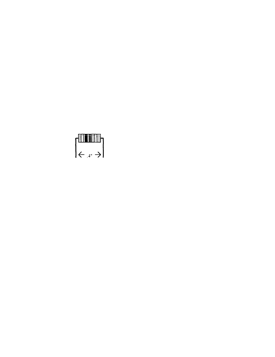
11. Locate resistor R1. This is a 1.82M resistor (brown-gray-red-N
-
ellow
brown).
Carefully bend the leads close to the resistor body to form right-angles (see
following diagram).
12. Insert RI into its mounting holes so the resistor body rests against the
board. Solder in place and trim the leads.
13. Locate resistor R2. This is a 1.82M resistor (brown-gray-red yellow-
brown). Carefully bend the leads close to the resistor body as in Step
#11.
14. Insert R2 into its mounting holes so the resistor body rests against
the board. Solder in place and trim the leads.
15. Locate resistor R3. This is a 1.82M resistor (brown-gray-red-
yellow brown). Carefully bend the leads close to the resistor body as in
Step #11
16. Insert R3 into its mounting holes so the resistor body rests against
the board. Solder in place and trim the leads.