Vectronics SWR-584C User Manual
Page 12
SWR-584C Instruction Manual
HF/VHF/220MHz SWR Analyzer
12
Sign Ambiguity: In Inductance mode, the analyzer measures reactance (X) and the operating
frequency, and then mathematically computes Inductance in uH. However, the processor can't
determine if the reactance sign is positive (+X
L)
. When in doubt, tune the VFO up in frequency
and see if the value of X increases. If it does increase, the device is likely inductive because
reactance exhibited by an inductor normally increases with frequency.
Standard vs Measured Value: The Standard Value for most inductors is determined at low
frequency (often in the kHz region). At RF, the value in uH may measure substantially different
because of stray capacitance between windings and other parasitic influences such as lead
capacitance or even the coil's proximity to other objects. Typically, the value in uH will increase
with frequency as the device moves closer to self-resonance. At self resonance, the inductor
looks like an open circuit (or a trap), exhibiting infinitely high reactance. Conversely, at some
very low frequency, it may look like a dead short.
4.6 Frequency Counter Mode: This function makes the analyzer's frequency readout circuitry
available as a discrete frequency counter for your test bench. Like many counters, sensitivity
for "locked-up" readings gradually decreases at higher frequencies. At HF, the measurement
threshold is under 10 mV-pp, but gradually increases to nearly 200 mV-pp at 230 MHz. The
"never-exceed" input voltage for safe testing is 2.0 V-pp.
Important Warning: Never exceed 2-Volts peak-to-peak or apply a DC voltage to the
Counter Input. Also, never connect a transmitter or unknown signal source to the input.
To access the counter function:
[ ] Turn on the analyzer and allow it to boot to default mode (R&X).
[ ] Press Mode four times to access Freq. Counter and wait for the working screen.
[ ] Connect your signal source to the BNC-Female Frequency Counter Input connector.
[ ] Read Frequency in MHz and Gate time in seconds (0.1s) on the top line of the display.
The default gate speed is 0.1 second, providing 1-kHz resolution. Other options are .01
second (very fast gate) with 10-kHz resolution and 1.0 second (slow gate) with 100-Hz
resolution. To change the Gate speed:
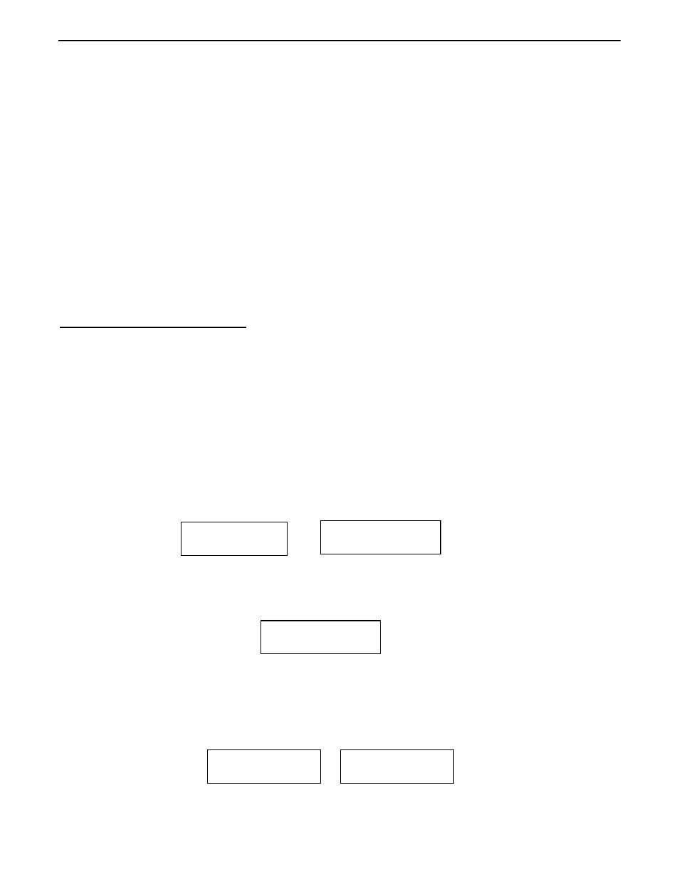
[ ] Press Gate once for .01-sec gate time. Two screens appear in rapid succession:
Freq. Counter
Gate Time .01s
000.000 MHz 0.1s
Freq. Counter
146.700 MHz 0.1s
Freq. Counter
146.70 .01s
Freq. Counter