Name & function of each part – TVLogic LVM-091W-M User Manual
Page 12
REMOTE (RJ-45)
- Provides connection to control equipment for external monitor control.
- Features can be changed in the [REMOTE] section of OSD menu.
DVI DIGITAL/DVI ANALOG (DVI-I)
- Input connection for DVI digital/analog.
SDI-A/SDI-B (BNC)
- HD/SD-SDI signal input terminal.
TALLY(LAMP)
- Interlocks with front tally lamp.
SDI-OUT (BNC)
- HD/SD-SDI signal output terminal.
CVBS1/G/Y/S-Y (BNC)
- Signal input terminal used to feed the monitor COMPOSITE 1, S-VIDEO Y, COMPONENT Y and RGB
G signals.
CVBS2/B/Pb (BNC)
- Signal input terminal used to feed the monitor COMPOSITE 2, RGB B and COMPONENT Pb signals.
CVBS3/R/Pr/S-C (BNC)
- Signal input terminal used to feed the monitor COMPOSITE 3, S-VIDEO C, COMPONENT Pr and
RGB R signals.
AUDIO IN (phone jack)
- Internal speakers stereo audio input terminal.
AUDIO OUT (phone jack)
- Built in audio disembedder and internal speakers stereo audio output using mini jacks.
FACTORY PGM (40 pins)
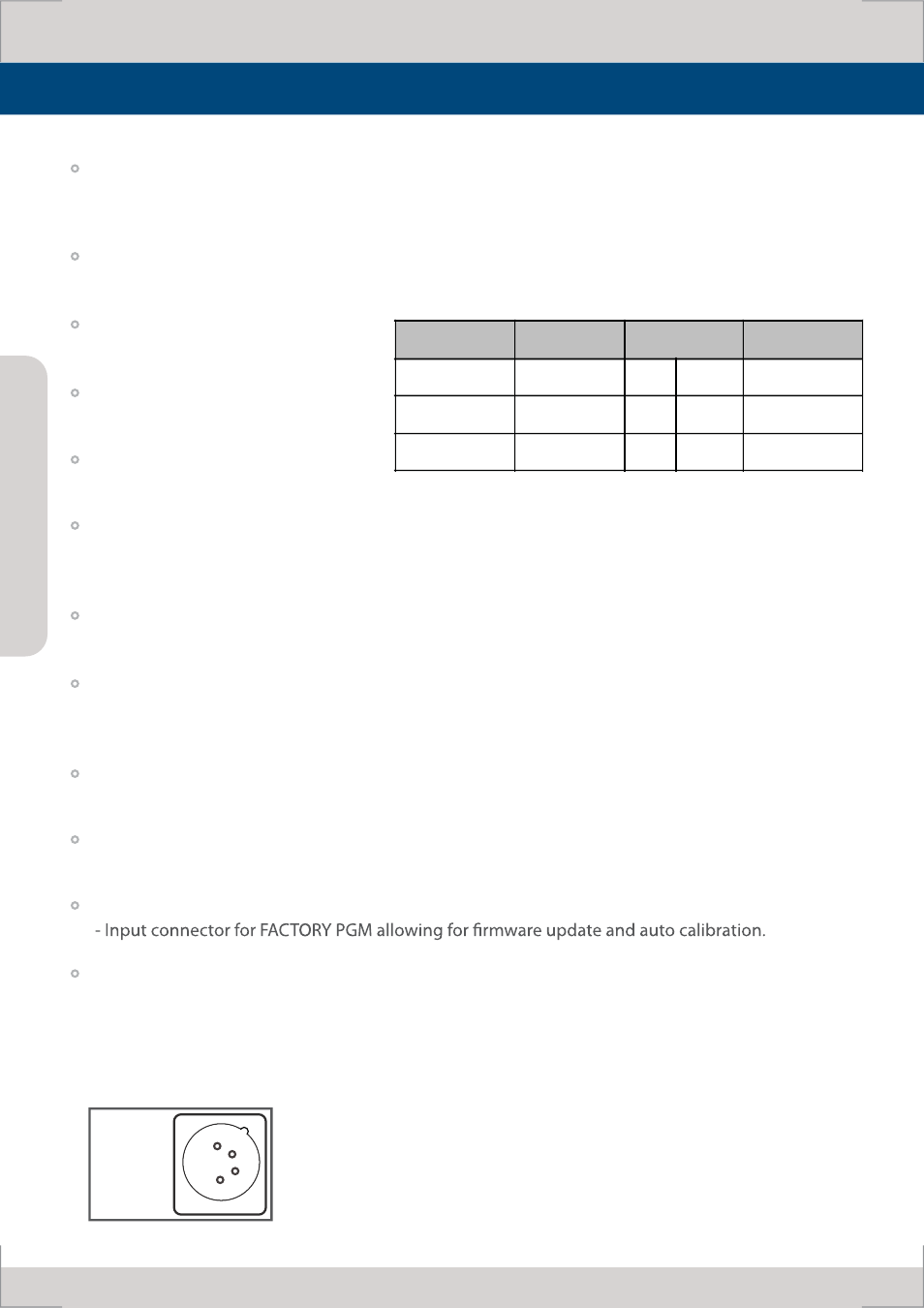
DC IN (XLR, 4 pins)
- DC 12V/24V.
The unit may not operate properly if the input line is connected before the GND is connected.
Connector
Composite
Component
S
Video
1
CVBS 1
Pb
B
No Con.
2
CVBS 2
Y
G
Y
3
CVBS 3
Pr
R
C
DC IN
socket
1: GND
4: +12V/
+24V
1
2
3
4
M
ul
ti F
orm
at
L
CD M
oni
to
r
12
Name & Function of Each Part