Displayport – NEXCOM ICES 667 User Manual
Page 42
Copyright © 2013 NEXCOM International Co., Ltd. All Rights Reserved.
28
ICEK 667-T6 Starter Kit User Manual
Chapter 2: Jumpers and Connectors
Pin
Definition
Pin
Definition
1
+5V_USB
2
USB_2N_C
3
USB_2P_C
4
GND
5
USB3_RX2_N_C
6
USB3_RX2_P_C
7
GND
8
USB3_TX2_N_C
9
USB3_TX2_P_C
10
+5V_USB
11
USB_3N_C
12
USB_3P_C
13
GND
14
USB3_RX3_N_C
15
USB3_RX3_P_C
16
GND
17
USB3_TX3_N_C
18
USB3_TX3_P_C
MH1
RGND
MH2
RGND
MH3
RGND
MH4
RGND
USB2
Pin
Definition
Pin
Definition
19
V25_LA1
20
LAN2_MDI0P
21
LAN2_MDI0N
22
LAN2_MDI1P
23
LAN2_MDI1N
24
LAN2_MDI2P
25
LAN1_MDI2N
26
LAN2_MDI3P
27
LAN1_MDI3N
28
GND
29
+3.3VSBY
30
LAN2_LED_ACT#
31
LAN2_LED_LINK100#
32
LAN2_LED_LINK1G#O
MH5
RGND
MH6
RGND
MH7
RGND
MH8
RGND
LAN2
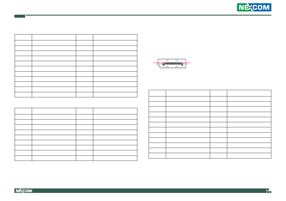
DisplayPort
Connector type: DisplayPort
Connector location: DDI2 and DDI3
Pin
Definition
Pin
Definition
1
DP2_CN_LANE0P
2
GND
3
DP2_CN_LANE0N
4
DP2_CN_LANE1P
5
GND
6
DP2_CN_LANE1N
7
DP2_CN_LANE2P
8
GND
9
DP2_CN_LANE2N
10
DP2_CN_LANE3P
11
GND
12
DP2_CN_LANE3N
13
DP2_CONFIG1
14
DP2_CONFIG2
15
DDI2_CTRLCLK_AUXP
16
GND
17
DDI3_CTRLDATA_AUXN
18
DP2_HPD_C
19
GND
20
+3.3V
MH1
RGND
MH2
RGND
MH3
RGND
MH4
RGND
DDI2
2
1
19
20