11 alarm relay output – KBC Networks ESML3-FL2-D4 User Manual
Page 11
Ethernet Switch User Manual
Manual_hw-ESML3-FL2-D4-Rev1011
Copyright © KBC Networks Ltd.
Page 11 of 18
www.kbcnetworks.com
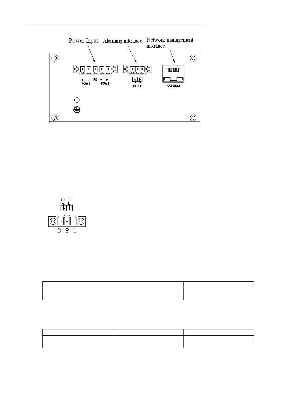
Figure 2.3 Power Input Terminals
2.11 Alarm Relay Output
The alarm terminal, which is also a green screw block terminal, (see Figure 2.3) has
two relay outputs and is used to indicate if there is a problem with the power supply
to the switch, this function must be enabled using the management software.
Figure 2.4 Alarm Terminal
2.11.1
Single Power Supply Connected:
Contacts
Power On
Power Off
1 & 2
Open
Closed
2 & 3
Closed
Open
2.11.2
Dual Power Supplies Connected:
Contacts
Power On
Power Off
1 & 2
Closed
Open
2 & 3
Open
Closed
See also other documents in the category KBC Networks Computer Accessories:
- FTL1-S1A-B-MSE (10 pages)
- MCG1-S2-BS (8 pages)
- ThruLink SP (2 pages)
- VPS Solar Power Kits (12 pages)
- MiniLink (15 pages)
- Mesh2HT (59 pages)
- MeshII (2 pages)
- WES (19 pages)
- WES (18 pages)
- WES2HT 17dBi Point-to-Point Client / Host 5GHz (2 pages)
- WES2HT 2/5dBi Point-to-Multipoint Host with PoE (2 pages)
- WES2HT 9dBi Multipoint Host (2 pages)
- WESII 9dBi to 9dBi Kit (5 pages)
- WESIIKT V221 17dBi to 17dBi Kit (4 pages)
- H.264 Encoder (2 pages)
- H.264 Encoder (49 pages)
- MPEG-4 Decoder (2 pages)
- MPEG-4 Encoder (2 pages)
- MPEG4 Decoder (29 pages)
- MPEG4 Encoder (33 pages)
- WES2HT (142 pages)
- ESUL6-FL2 (20 pages)
- ESML6-FL2 (64 pages)
- ESML6-P3 (49 pages)
- ESML6-P3 (51 pages)
- ESML6-P3 (17 pages)
- WESII (141 pages)
- ESUG4P-PG2 (15 pages)
- ESUG8P (14 pages)
- ESUL4-FL1 (17 pages)
- ESUL5 (15 pages)
- ESML8P-PC2 (110 pages)
- ESUL8 (14 pages)
- ESUL5P (14 pages)
- EE2CL (19 pages)
- ESUL8P-PC2 (15 pages)
- EE1CL (17 pages)
- EE1R3 (12 pages)
- FCHA1-M1T-R-WSB (13 pages)
- FDVA2-S2T-R-WSC (11 pages)
- Compact Transceiver (36 pages)
- FDVA4-DB1-S1T-R-WSC (14 pages)
- 3U Chassis Transceiver (40 pages)
- FDVA4-S1T-R-WSC (11 pages)