10 power input terminals – KBC Networks ESML3-FL2-D4 User Manual
Page 10
Ethernet Switch User Manual
Manual_hw-ESML3-FL2-D4-Rev1011
Copyright © KBC Networks Ltd.
Page 10 of 18
www.kbcnetworks.com
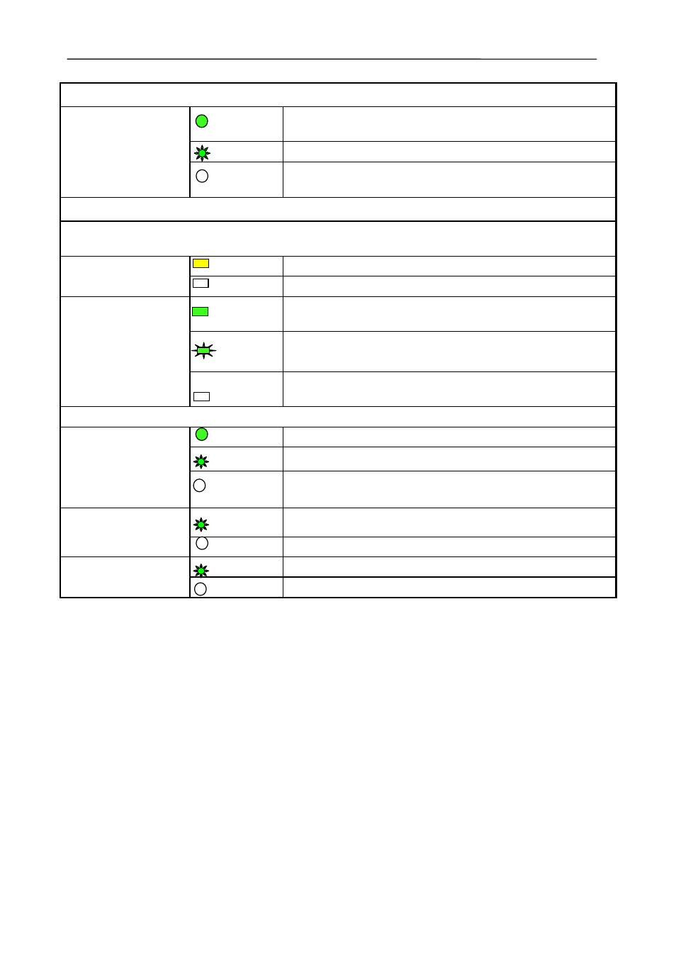
100M Optical Fiber Ports LED (1 & 2)
LINK/ACT
ON
Effective network connection has been established for
the port
FLASH
Data traffic is passing through the port
OFF
No effective network connection has been established for
the port
Ethernet RJ45 Port Status LED (3,4 & 5)
Each RJ45 Ethernet port has two indicators, a yellow lamp and a green lamp. The yellow lamp
indicates port speed, and the green lamp indicates port link state.
10/100 (Yellow)
ON
100M working status(100Base-TX)
OFF
10M working status(10Base-T)
LINK/ACT
(Green)
ON
Effective network connection has been established for
the port
FLASH
Data traffic is passing through the port
OFF
No effective network connection has been established for
the port
Data Ports
ALARM
ON
IP address conflict
FLASH
Data port CPU operating correctly
OFF
Normal operation
T
FLASH
Data being transmitted
OFF
No data transmission
R
FLASH
Data being transmitted
OFF
No data transmission
*
Note
: the power alarm must be active in the GUI.
2.10 Power Input Terminals
The ESML3-FL2-D4 has two green screw terminal blocks (Power Input 1 & Power
Input 2) mounted on the top panel of the switch, see Figure 2.3. The power inputs
can be used independently or they can be connected to two separate external 24V
DC power supplies to provide redundancy. The red sleeved wire should be connected
to the +ve power input and the blue sleeved wire should be connected to the –ve
power input of the green male screw block terminal.