System and power connection, Wired models, Touch panels and controllers – CUE smartCUE Interfaces User Manual
Page 8: Power supply ethernet cable poe adapter, Ethernet touch panels and controllers, Ethernet cable ethernet with poe
8
smartCUE Interfaces | User Manual | System And Power Connection
© CUE, a.s. All Rights Reserved. | www.cuesystem.com | [email protected]
System And Power Connection
Wired Models
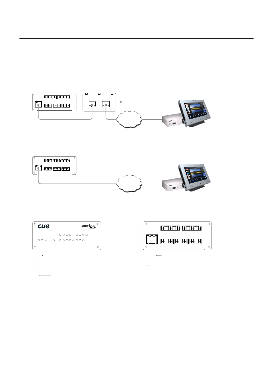
All wired interfaces are connected using 10/100 BaseT LAN communication and Power over Ethernet (PoE)
power supply.
For networks without PoE infrastructure it is necessary to use PoE Adapter compliant with IEEE802.3af
standard. PoE adapter isn’t part of interface delivery. Recommended model is Cue’s PoE Adapter PSA16U,
product code CS0327.
Touch panels and controllers
Following picture describes connection for network equipped with PoE IEEE802.3af infrastructure.
1 2 3 4 5
SERIAL
DIGITAL I/O
5 6 7 8 G
S S S S G
1
1 2 3 4 G
S G S G S G S G
IR/SERIAL
1
2
3
4
S G S G S G S G
GENERAL I/O
1
2
3
4
default IP address
192.168.1.254
LAN (PoE)
S S S S G
Power supply
Ethernet cable
PoE Adapter
OUT
IN
Ethernet
Touch panels and controllers
1 2 3 4 5
SERIAL
DIGITAL I/O
5 6 7 8 G
S S S S G
1
1 2 3 4 G
S G S G S G S G
IR/SERIAL
1
2
3
4
S G S G S G S G
GENERAL I/O
1
2
3
4
default IP address
192.168.1.254
LAN (PoE)
S S S S G
Ethernet cable
Ethernet
with PoE
1 2 3 4 5
SERIAL
DIGITAL I/O
S S S S G
5 6 7 8 G
S S S S G
1
1 2 3 4 G
S G S G S G S G
IR/SERIAL
1
2
3
4
S G S G S G S G
GENERAL I/O
1
2
3
4
default IP address
192.168.1.254
LAN (PoE)
Ethernet activity yellow indicator
Ethernet link green indicator
PWR LINK
F.
D.
SERIAL
DIGITAL I/O
1
1
2
3
4
5
6
7
8
1
2
3
4
IR/SERIAL
1
2
3
4
GENERAL I/O
Ethernet green indicator
• Link
• Activity (active = no light)
Power blue indicator
Following picture describes power and network indicators common for all wired models.