Installation, Power-up test procedure, Wiring diagram absence detection – CP Electronics EBDSPIR-PRM-2CH-LV User Manual
Page 3
3
Installation
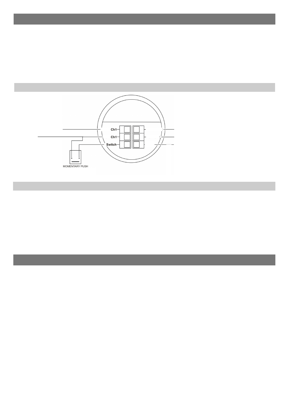
To use absence detection a retractive (momentary) switch must be connected between the 2 terminals on the
diagrams. Note that this will be switching mains voltage.
The unit ships with presence detection as default. To change to absence detection, press and release the external
switch 5 times within the first minute of power up. The LED will turn on solid for 30 seconds to indicate absence
mode has been selected.
To change back to presence detection, repeat the above procedure—the LED will flash for 30 seconds to indicate
presence mode has been selected.
Note: the above adjustments can also be made using the UHS5 or UNLCDHS handsets. See Programming sections.
When power is applied to the unit, the load will turn on immediately.
Set the timeout to 10 seconds, vacate the room or remain very still and wait for the load to switch off .
Check that the load switches on when movement is detected.
The unit is now ready for programming.
Power-up test procedure
Choosing a Suitable Location
The EBDSPIR-PRM-2CH-LV is designed to be ceiling mounted and must satisfy the following criteria:
Avoid positioning the unit where direct sunlight may enter the sensor element.
Do not site the sensor within 1m of any lighting, forced air heating or ventilation.
Do not fix the sensor to an unstable or vibrating surface.
Note +/In Ch1 is used to supply the detector with power.
CH1 and CH2 plugs are coded.
Ensure that the plugs are
inserted correctly and do not
apply excessive force
Wiring Diagram
Absence detection
VF
Switched
output
Supply
Common(-)
COM
In Ch2
Out Ch2
Out
+/In
Switched
output
DC Supply
11.5VDC-36VDC
or
AC Supply
10VAC-26.5VAC
Optional for presence,
mandatory for absence detection