Installation, Readback function, Unlcdhs handset only) – CP Electronics EBDSM-PRM User Manual
Page 4: 2a 3
4
Installation
The UNLCDHS has the ability to read back the settings stored in a device.
To read back individual parameters
Navigate to the parameter and press the ‘R’ (Read) button whilst pointing at the device. The handset will click
when the parameter has been read back, the device will flash its LED, and the value will be shown against the
parameter in the menu.
To read back all of the parameters in a menu
Press and hold the ‘R’ (Read) button for more than 1 second.
The handset will click every time a parameter is received
The device will show multiple flashes of its LED
All of the values will be shown against the parameters in the menu.
The individual parameters may be edited and then saved as a ‘Macro’.
Notes
If a parameter(s) has been missed because of a communication error, the missing value(s) is replaced by dashes.
When reading back, the Channel 1 relay (where fitted) will temporarily be switched off, and will return to it’s
normal state 2 seconds after the read back has been completed.
Readback function
(UNLCDHS handset only)
The EBDSM-PRM is designed to be ceiling mounted and must satisfy the following criteria:
The sensor should be sited so that the occupants of the room fall inside the detection pattern overleaf, at a
recommended height of 2.8m on the ceiling. Note that the lower the sensor is installed the smaller the detection
range will be, subject to the parameters shown on the diagram.
Avoid positioning the sensor where direct sunlight may enter the sensor element.
Do not site the sensor within 1m of any lighting, forced air heating or ventilation.
Do not fix the sensor to an unstable or vibrating surface.
Choosing a suitable location
Gasket
(optional)
Mounting
plate
Sensor
Head
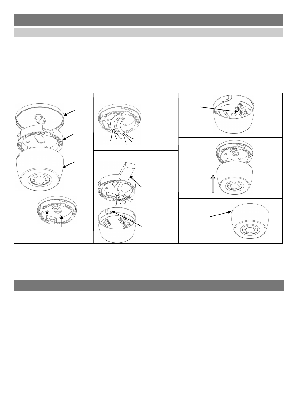
Components
2a
3
Rear entry
Pass cable through
Gasket and Mounting
plate
Side entry
Pass cable through
either of the 2 side
entry points in the
Mounting Plate
Screw the Mounting plate and optional Gasket to the
ceiling via the 4 mounting holes.
Note: 2 holes are suitable for BESA boxes, 2 are
suitable for UK or EU 60mm fixing backboxes.
Wire cables
into the
terminals
Push the Sensor
Head onto the
Mounting Plate and
align clips with
slots on Sensor
Head
Use a flat bladed
screwdriver to unclip
the Mounting Plate from
the Sensor Head
4
1
Conduit
5
2b
Knock-outs on Sensor
Head for clearing side
entry of conduit and /
or cables