COMMELL FS-97A User Manual
Page 26
FS-97A User’s Manual Hardware Setup
Display Interface
26
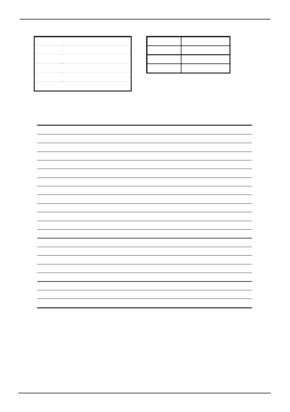
Connector: CN_INV
Connector: JVLCD
Type: 5-pin LVDS Power Header
Type: 3-pin Power select Header
Pin Description
Pin Description
1 +12V
1 VCC
2 GND
2 LCDVCC
3 GND
3 VCC3
4 GND
5 ENABKL
Connector: CN_LVDS
Type: onboard 40-pin connector for LVDS connector
Connector model: HIROSE DF13-40S
Pin Signal
Pin Signal
2 LCDVCC
1 LCDVCC
4 GND
3 GND
6 ATX0-
5 BTX0-
8 ATX0+
7 BTX0+
10 GND
9 GND
12 ATX1-
11 BTX1-
14 ATX1+
13 BTX1+
16 GND
15 GND
18 ATX2-
17 BTX2-
20 ATX2+
19 BTX2+
22 GND
21 GND
24 ATXCK-
23 BTX3-
26 ATXCK+
25 BTX3+
28 GND
27 GND
30 ATX3-
29 BTXCK-
32 ATX3+
31 BTXCK+
34 GND
33 GND
36 PANELCLK 35 N/C
38 PANELDATA 37 N/C
40 N/C
39 N/C
To setup the LCD, you need the components below:
1. A panel (support up to 24-bit dual channel) with LVDS interfaces.
2. An inverter for panel’s backlight power.
3. A LCD cable and an inverter cable.
For the cables, please follow the pin assignment of the connector to make a cable, because
every panel has its own pin assignment, so we do not provide a standard cable; please find
a local cable manufacture to make cables.