Connection of the capacitor bank to the mains, Power circuit – CIRCUTOR OPTIM-EMS-C Series User Manual
Page 13
3.4.-CONNECTION OF THE CAPACITOR BANK TO THE MAINS
Check that the rated voltage of the capacitor bank matches the voltage between
phases of the mains to which it is being connected.
For more information see section “
” and check the label for
the voltage value
Un and the rated frequency fn of the EMS-C capacitor bank.
For feeding cables into the capacitor bank cabinet, always use the entry point
enabled for this purpose, located on the left side of the cabinet base (relative to
the front panel).
Do not cut holes in other parts of the cabinet for feeding cables through or for
installing support brackets.
It may produce trimmings that can cause short-circuits.
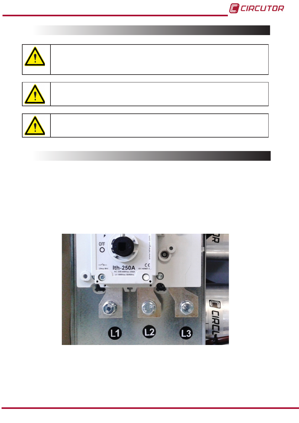
3.5.-POWER CIRCUIT
Connect input terminals L1, L2 and L3 (power circuit) to the mains using a cable with a suitable
cross-section, in accordance with the LVR, ITC-BT-19.
Generally, the cables of the phases are according to the following colour code: L1 (black), L2
(brown), L3 (grey).
To determine the size of the phase cables, the maximum nominal current I
max
shown on the unit
label, and a transients overload of up to 1.5 times I
max
must be taken into account.
Figure 6: Input terminals L1, L2, and L3 for the connection of the OPTIM EMS-C capacitor banks to the mains.
13
Instruction Manual
OPTIM EMS-C series