CIRCUTOR computer SMART Series (Available until stock) User Manual
Page 10
M98235701-03-12A
Computer Smart 6/Computer Smart 12
- 9 -
2.2.3
Cable sections and protection elements
The power circuit must be protected with gl (IEC 269) or M type fuses (IEC 127) with a rating of 0.5 to 2 A. A
circuit breaker or equivalent device must be used to connect and disconnect all of the unit's control circuits
(Computer Smart power supply + relay circuits and contact coils) from the power supply grid. The circuit
breaker must be installed on the equipment and be easy to access. The power circuit and relay contact
circuits must be connected with cables with a minimum section of 1.5 mm
2
. The cables of the current
transformer's (CT) secondary must have a minimum section of 2.5 mm
2
. In the case of distances between the
CT and the regulator over 25 m, this section must be increased by 1 mm
2
for every 10 m.
2.2.4
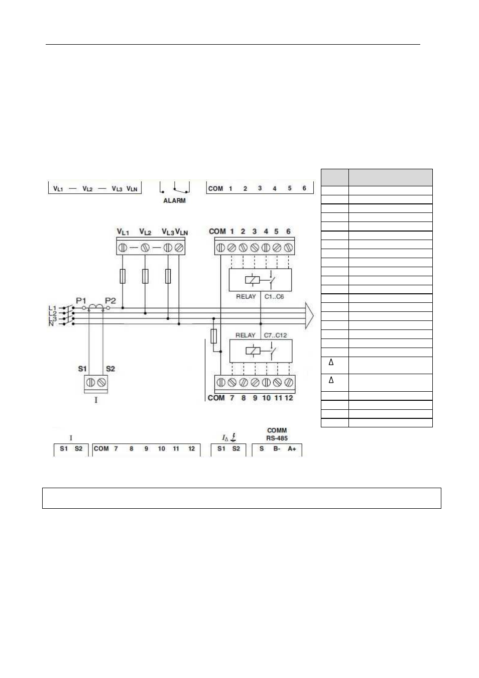
Connection diagrams. Computer Smart 6/12.
Fig. 2.2.- Computer Smart 6/12 Connection diagram
(*) Nominal voltage, depending
on the type. See label on the
unit.
No.
Description of the
terminals
U
L1
Voltage input L1 (*)
U
L2
Voltage input L2 (*)
U
L3
Voltage input L3 (*)
U
N
Voltage input LN (*)
COM
Relay common
1
Relay output 1
2
Relay output 2
3
Relay output 3
4
Relay output 4
5
Relay output 5
6
Relay output 6
7
Relay output 7
8
Relay output 8
9
Relay output 9
10
Relay output 10
11
Relay output 11
12
Relay output 12
I S1
Current input S1
I S2
Current input S2
I S1
Leakage current input
S1
I S2
Leakage current input
S2
A+
RS-485 Input A(+)
B-
RS-485 Input B(-)
S
RS-485 S Input
ALARM
NC or NO Relay output
NOTE: The two COM terminals are not internally connected. In the case of the model with 12 relay outputs,
the two COM outputs of the regulator must be short-circuited.
Only for
Smart
computer
12