Installation and connection – AXING SKQ 4-01 User Manual
Page 6
Operation Instructions SKQ 4-01
Chapter 2: Installation and connection
6
© AXING AG • Swizzerland • Reserving change in design and type - We cannot be held liable for printing error
12.09.11
2
Installation and connection
The SKQ 4-01 can either be operated in a head ends basic unit SKS x-xx or in stand alone mode. SAT
ZF signals of the LNB(s) are either provided through optionally available input distributors, a multiswitch
or directly to SAT ZF inputs.
Maximum total current of LNB connector is 250 mA.
2.1
Installation and connection in a headend base unit
If you want to operate the SKQ 4-01 on a head ends basic unit SKS x-xx, plug the twin module into the
output collection field and fasten it by screws. Each free slot may be used. The power supply unit
supplies the module via the output connection field.
For detailed information on the headend base unit, refer to whose operating instructions.
Before inserting or changing a module, pull the mains plug of the head ends basic unit from the
socket! Ground the base plate in order to avoid dangerous overvoltages (attention: risk of fire/death).
Important
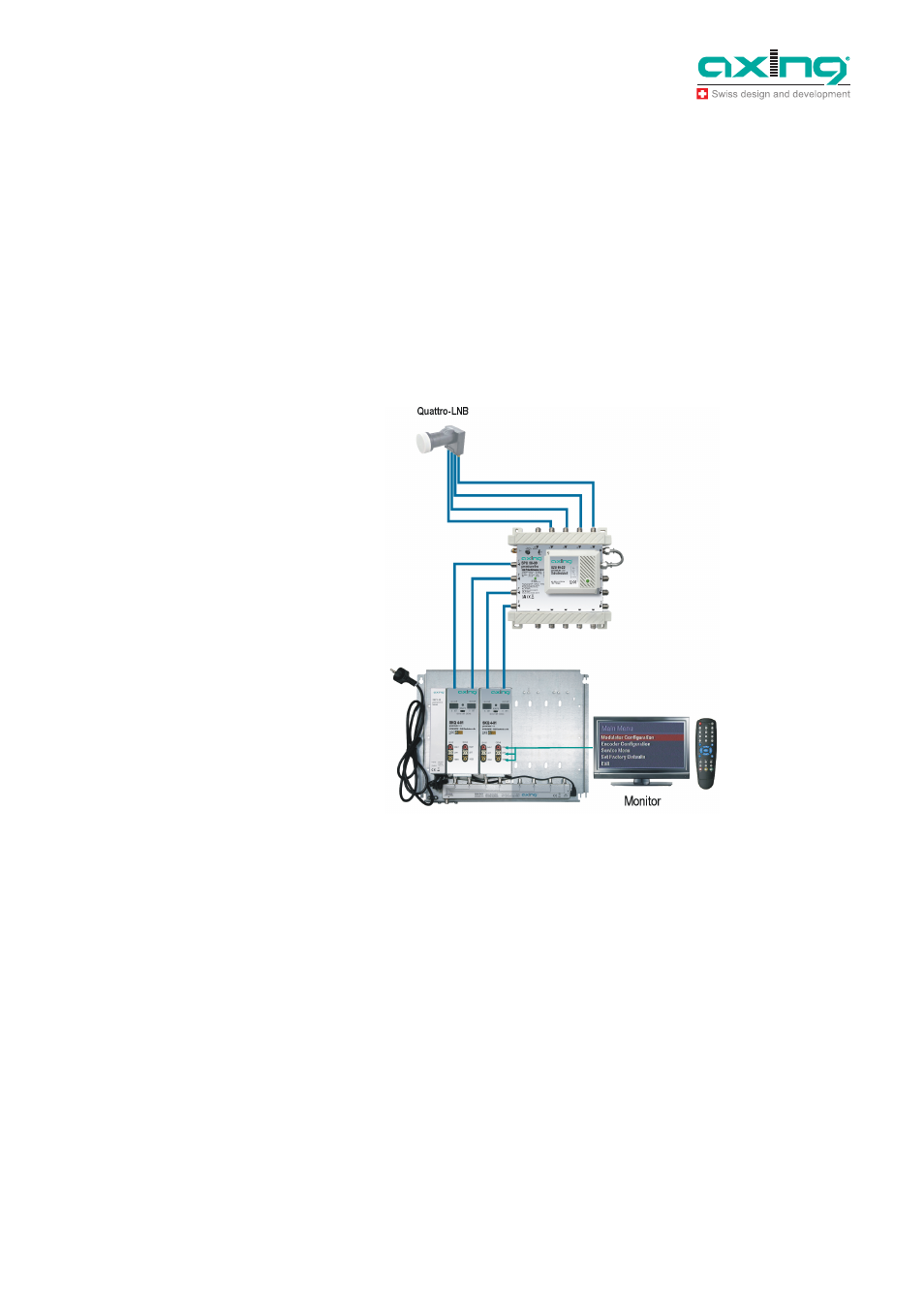
Fig. 3: Installation and connection
in a headend base unit
Hinweise