ABUS Technologies Log Box-DA Data Logger User Manual
Page 15
ABUS TECHNOLOGIES INC.
15
Log Box-DA
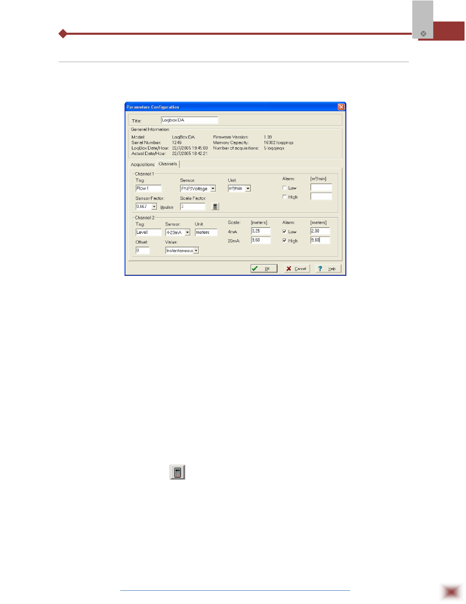
6.5 Channels Field
By selecting the “Channels” option, the user is able to choose the individual settings for each
input channel, as Figure below shows.
Parameters for Input Channels Configuration
6.5.1 CHANNEL 1 – DIGITAL PULSE LOGGINGS
Configuration options provided for Channel 1 are:
Tag:
Defines a name (up to 8 characters) for identifying the variable to be measured.
Sensor:
Selects the input type of the channel: Unabled, PNP/Voltage, NPN, Dry Contact
Unit:
Defines the input variable unit. Flow measurement is default, however, other units
can be defined by typing the unit in the text box.
Sensor Factor:
Defines the amount of input per pulse. Liquids flow measurement is default (liters
per pulse.) It can assume any value between 0.000001 and 16383.
Scale Factor:
Adjusts the readings such as to represent a particular flow measurement unit.
This factor can be automatically calculated (the software computes the value
taking into account the interval between loggings and the sensor factor) by using
the button
. It can assume values between 0,000001 and 65535.
Alarm:
The routines for alarms LOW and HIGH are executed at the end of the logging
period, informing the occurrence of an alarm by flashing the alarm LED in the
front panel.
LOW defines the minimum value under which the alarm is triggered; HIGH defines the
maximum value above which the alarm is triggered. Once activated, the alarm LED indicator stays so
even after the alarm-triggering situation has ceased.