Installation – ABUS Technologies Log Box-RHT with LCD Data Logger User Manual
Page 6
ABUS TECHNOLOGIES INC.
6
Log Box-RHT
4. INSTALLATION
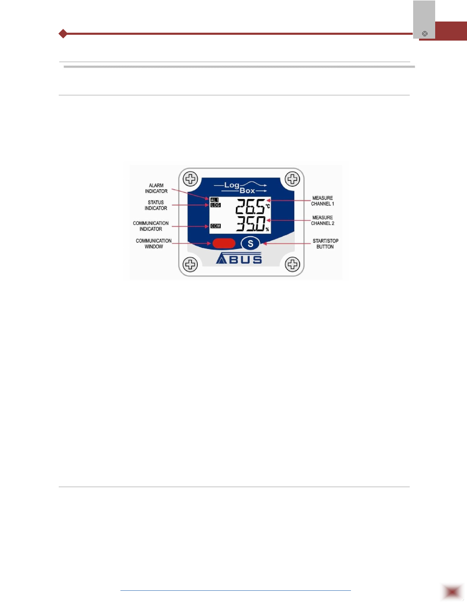
4.1 Panel
The identification label is on the logger body. Check if the features described are in accordance
with your order. The RHT model is designed to measure temperature and relative humidity. The
following elements are shown in the Figure Logger Front, below:
Logger Front
START / STOP button:
Can be configured to start or stop logging when pressed. It can be
also used to browse and change screens.
IR Communication Window:
Activated when there is a communication attempt or when
communication between logger and PC/Palm is activated.
State indicator (LOG):
Indicates when the device is logging.
Alarm Indicator (AL1 / AL2):
Warns the user as to alarm conditions. It remains active whenever an
alarm condition occurs, until a new configuration is applied to the
logger.
Channel Indicator:
Indicates the channel selected.
Battery Indicator:
The battery symbol is shown when the battery voltage is low.
MIN/MAX Values Indicator:
Minimum and Maximum value of each channel during readings.
4.2 USB Driver Installation
The drives installation steps may vary according to the machine, even for the same version of an
operating system. The following screenshots and steps are only to provide guidance.
1. Insert the CD shipped with the logger in the CD-ROM drive.
2. Connect the serial communication interface IrLink-3 to the PC USB port. Windows® will
acknowledge the presence of new hardware and a few seconds later it will start the drivers
installation process.