Installation – ABUS Technologies TAGTEMP Data Logger User Manual
Page 5
ABUS TECHNOLOGIES INC.
5
TagTemp
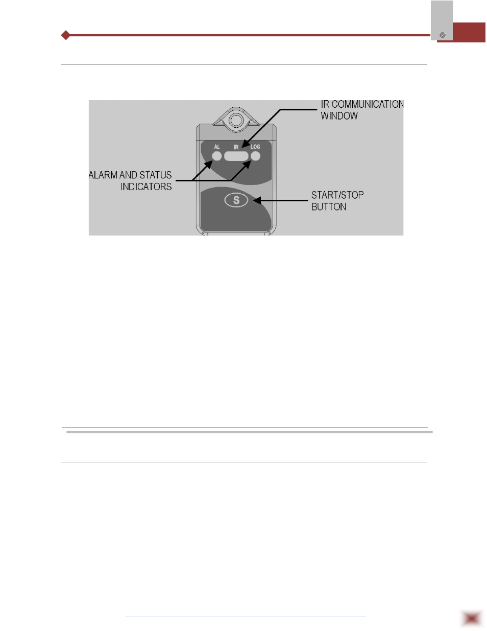
2.2 Panel Identification
The identification label is on the logger body. Check if the features described are in accordance
with your order. The following elements are shown in the logger front.
Logger Panel
Start/stop button (S):
This button “wakes up” the logger whenever a communication between
logger and PC is intended to start. It can also be configured to start or
stop the temperature measurement process.
IR communication Window: PC - Logger communication area. During download, the communication
interface must be directed towards this window.
Status indicator (LOG):
While in stand-by (not logging) or after a series of measurements, it
flashes once at every four seconds. During logging it flashes twice at
every four seconds.
Alarm Indicator (AL):
Warns the user as to alarm conditions. Whenever an alarm situation
takes place it will flash once at every four seconds, until a new
configuration is applied to the logger.
3. INSTALLATION
3.1 Recommendation
1. Signal wires should be installed in grounded conduits and away from power or contactor wires.
2. Instruments must be powered only by an exclusive power supply.
3. System failure should always be taken into account when designing a control panel to avoid
irreversible damage to equipment or people.
4. Installing RC filters (47R and 100nF, serial) is strongly recommended at contactor coils or any other
inductors.