Rht 5. connections – ABUS Technologies RHT WM with LCD Датчики User Manual
Page 8
ABUS TECHNOLOGIES INC.
8
RHT
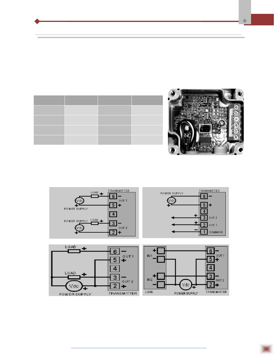
5. CONNECTIONS
The transmitter can be ordered as 4-20 mA current output or 0 to 10 Vdc
voltage output. The output signal is defined on purchase and cannot be later changed.
Variables can be monitored together or separately. Combinations of mobile jumpers
J4 and J5 within the transmitter case define how variables will be used. The jumpers
also define the transmitter terminals with available output signals.
J4 and J5 position within the transmitter
Figures below shows the required electrical connections:
LOAD represents the output signal measurement equipment (controller, register, etc).
The connection wires go inside the transmitter through to the cable gland mounted in
the transmitter case.
Jumper J5
Jumper J4
OUT1
OUT2
Position A
Position A
Temperature
Humidity
Position A
Position B
Temperature
Off
Position B
Position A
Humidity
Off
Position B
Position B
Humidity
Temperature
Configuration of OUT1 and OUT2 outputs
4-20 mA connections
0-10 VDC connections
4-20 mA connections with single source
04-20 mA model with single source and load with
two input channels