Fieldbus network, 6 fieldbus network – Datalogic Scanning DS6300 User Manual
Page 63
INSTALLATION
2
2.7.6 Fieldbus
Network
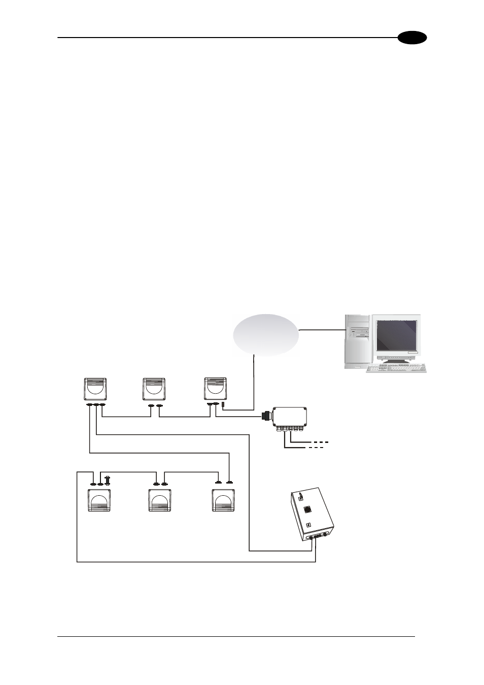
The Fieldbus Ethernet model offers connectivity without any converter or adapter needed.
The DS6300 master Fieldbus communicates with a remote host (for ex. remote PC
connected via Internet) by means of a cable connected to the Fieldbus connector provided. It
can be activated by a signal generated by the remote Host or by a physical presence sensor.
The external signals (trigger, encoder) are connected to the master through the C-BOX 100.
The master reader connects to the first slave reader of the system through the local
Lonworks 9-pin female connector. Fieldbus models are provided with an internal Lonworks
terminator.
The slave readers are connected together through the local Lonworks connectors. Only the
9-pin female connector of the last slave reader must be terminated by the BTK-6000
terminator.
The example below shows a system powered by the PWR-240 where multiple slaves are
connected through CAB-63XX power cable. The master and all slaves are connected
together through the CAB-610X cables.
The same network layouts are available as for the DS6300 standard model.
Fieldbus
Network
*
P.S. (Presence Sensor) connected to External Trigger/PS input.
**
C-BOX 100 modified to accept scanner power.
***
The Slave scanners are Master/Slave models, which allow Lonworks network propagation.
****
Encoder connected to IN2/ENC input.
Figure 62 – Fieldbus Small Synchronized Network
e 2***
e1***
Remote Host
CAB-60XX
Slave 5***
Slave 4*** Slave
3***
Slav
Slav
BTK-6000
PWR-240
CAB-63XX
Master
C-BOX 100**
PS*
Encoder****
CAB-610X
CAB-610X
CAB-63XX
CAB-610X
CAB-610X
CAB-610X
49