Datalogic Scanning DS6300 User Manual
Page 41
INSTALLATION
2
DS6300 9-pin Lonworks connector pinout
Pin Name
Function
1
CHASSIS
Cable shield internally connected by capacitor to chassis
9
VS
Supply voltage - positive pin
2
GND
Supply voltage - negative pin
6
VS_I/O
Supply voltage of I/O circuit
3
Ref_I/O
Reference voltage of I/O circuit
4
SYS_ENC_I/O
System signal
5 SYS_I/O
System
signal
7
LON A
Lonworks line (polarity insensitive)
8
LON B
Lonworks line (polarity insensitive)
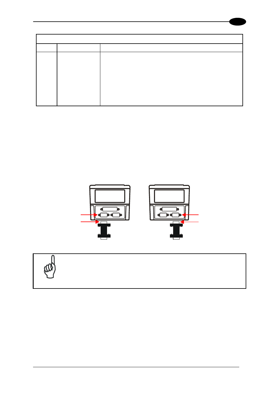
Network Termination
When building a Lonworks system the network must be properly terminated by positioning
BTK-6000 terminator in the DS6300 master reader and in the last DS6300 slave reader.
Each side of the terminator provides a different connector; thus, it can be inserted either into
the Lonworks 9-pin male connector of the master reader or in the Lonworks 9-pin female
connector of the last slave reader:
Slave
Master
Male
Female
Female
Male
Figure 33 - BTK-6000 Network Terminator
NOTE
For Fieldbus models no terminator must be inserted in the reader, since it
is internally integrated.
27