Nexen TA100 964400 User Manual
Page 9
5
FORM NO. L-20292-C-0700
2.
Connect a voltmeter to TP7 (COM) and TP1 (See
Figure 9).
3.
Rotate S1 clockwise to VDC, increasing the
reading at TP1 (Example: Maximum Tension = 100
Lbs. with a 50 Lb. weight, adjust the output for 5.0
VDC) (See Figure 9).
FIGURE 10
FIGURE 9
S1
S2
TP7
TP2
TP1
FIGURE 11
Jumpers
J3 and J4
S1
TP7
TP2
TP1
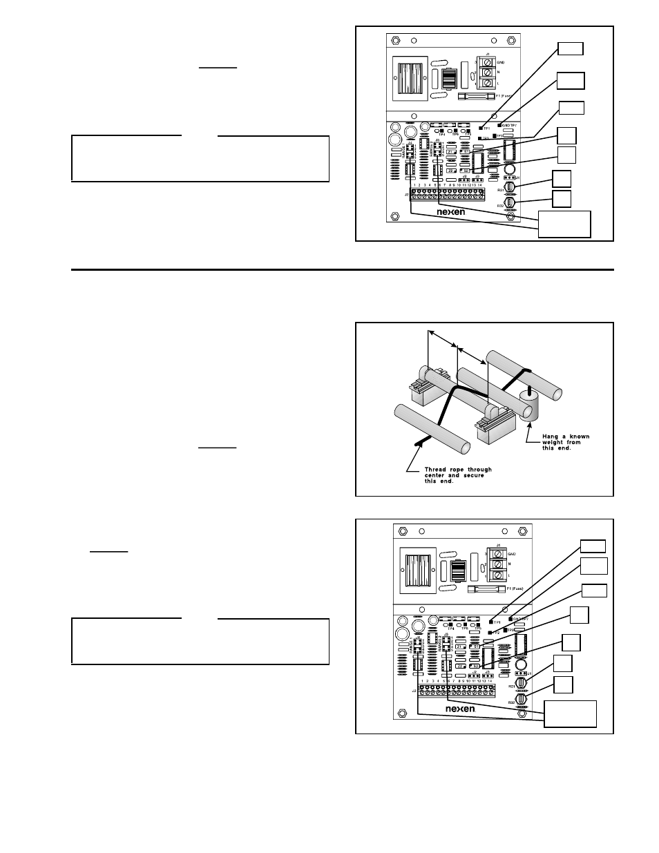
SPAN ADJUSTMENT (WITH TWO MB TENSION SENSORS)
1.
Thread a rope or narrow web over the Sensor Roll in the
normal path. Be sure the rope or web is at the center of
the Sensor roll; then, hang a known weight (within the
range of the system) on one end of the rope or web
(Example: Maximum Tension = 100 Lbs. hang a 50 Lb.
weight) (See Figure 10).
2.
Connect a voltmeter to TP7 (COM) and TP1 (See
Figure 11).
3.
Rotate S1 clockwise to VDC, increasing the
reading at TP1 (Example: Maximum Tension = 100
Lbs. with a 50 Lb. weight, adjust the output for 2.5
VDC) (See Figure 11).
4.
Connect a voltmeter to TP7 (COM) and TP2 (See
Figure 11).
5.
Rotate S2 counterclockwise until the voltmeter reads
VDC at TP2 (Example: Maximum Tension =
100 Lbs. with a 50 Lb. weight, adjust the output for
2.5VDC) (See Figure 11).
S2
NOTE
R31 and R32 are factory adjustments only. R31 is a
fine adjustment for the 0-10 VDC. R32 is a fine
adjustment for the 4-20mA.
NOTE
R31 and R32 are factory adjustments only. R31 is a
fine adjustment for the 0-10 VDC. R32 is a fine
adjustment for the 4-20mA.
R31
R32
R31
R32
Jumpers
J3 and J4